
Been a little silent on my blog regarding my Enterprise-refit project. But it isn’t because I haven’t been doing work on it. I have spent weeks now finally getting the 2-3 deck level 3D model accurate.
Getting the complex compound curves and shapes of the exterior of the bridge/2-3 deck superstructure was a real challenge. But I think I finally have the accurate baseline shapes to work with going forward.
This long-running work has yielded results that now reconciles the exterior of the original filming miniature of the Enterprise Officer’s Lounge window lines with the interior “set” miniature in 3D space.
Here’s a video showing it from within Moment of Inspiration (MoI) the 3D modeling software I have been using:

Video of the Enterprise-reft 2-3 deck 3D model work-inprogress.
The above is the preliminary baseline model of the superstructure. But now that I have these baseline shapes, I will be using it to work backwards to build out the longeron, stringers, spars and ribs, for the underlying structure of a presumed 23rd century take on semi-monocoque construction of the Enterprise-refit spaceframe.
I will be porting out the shapes in the 2D master blueprint drawings, then moving next to the interior work out the interior column/ribs on the inside of the window frames. Then the interior lounge walls and so forth.
When I posted this video last night and linked to it over at The Fleet Workshop website, one of the regulars there asked me to clarify when I mentioned the miniature, if I was talking about the lounge model, and not the full ship miniature, and if so, do the windows on the ship model match the detailing on the lounge model?
That lead to a lengthy answer about the couple of months work to get to this point in the superstructure model which might be instructive here in this blog entry.
There was a miniature “set” that was built 1/8th scale for the VFX filming of the interior view looking out the aft windows for the shuttle arrival scene in Star Trek: The Motion Picture Picture.
That is what these Leslie Ekker drawn blueprints are of:

Orignal blueprint plan of the Officer’s Lounge of the Enterprise, for ST:TMP.
Which were production plans for the interior miniature, which were made from (and detailed out) the original concept drawing done by Andrew Probert.
Then there was the exterior of the bridge/2-3 deck superstructure that was part of the 1/120th scale full miniature of the Enterprise herself.
The curvature baseline of the windows (top view) is a match visually to some of the reference of the exterior “ship” miniature and to the drawing of the interior “set” miniature.
That curved window baseline is shown just below the slanted kick-board “wall” that defines the sunken seating area surround and the raised planter areas. That slanted baseboard goes up at a 60º angle to a short 90º vertical section to join with the “window” wall that slants up as a back wall and curves upward and becomes the ceiling.
So those basically align and match, and I got those to match down to the millimeter (finally) after a lot of 3D modeling and adjusting
However the large dashed outer curvature line, which is labeled as indicating the “outside seam line for ref. only. do not build” in the interior “set” drawing is not accurate to the exterior of the superstructure.
The windows and entire lounge area is further aft in relation to the superstructure saucer seam line. That dashed reference seam line in the interior “set” miniature drawing is simply too far back from the windows to match the relative position in the exterior model. Hence that dashed lines curve is off as to shape/curve to the actual exterior seam.
Since it was only meant as a conceptual reference point—and wasn’t part of the interior miniature as built—I forgoed trying to somehow make it reconcile (which simply cannot be done as drawn) with the rest of the superstructure shape.
I let the exterior superstructure and saucer seam line land where it needed to be to match the distance up the slope for the baseline of the windows. That required taking into account the depth of the window “alcove” that goes around the superstructure and is inset into it.
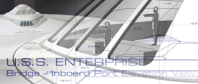
For the height of the windows, I went with the measured height of the aft view drawing of the interior, which was then projected back and “cut out” of the back sloping wall.
You can see what this describes in this screenshot. The magenta colored rectangle matches the measured height (converted into the same scale) taken from the Ekker interior “set” aft elevation drawing, which is then projected onto the sloping curved wall:

It pretty much aligns with the exterior miniature reference photos and placement. After considerable effort I managed to get a curvature that allows a rectangle (projected back) onto it and get it to match the interior wall seam (which you can see in the bottom view in that split view screenshot).
So that window baseline position and window height are what I ended up needing to use as the cross-reference point between interior and exterior.
Working back and forth to get the complex curves in all axis to wrap around the sloping back wall to match the minature profiles, and top view when it meets the saucer section—which is itself a shallow compound curve—was a bitch.Because that swept out shape has to intersect with the saucer—itself as complex subtle curved face—in such a way that it matches the top view exterior shape of the superstructure/saucer seam line. All while still matching the profile in curvature as it sweeps around and transitioning in such a way so that window baseline matches the interior drawing line, and exterior reference photos.
It has taken me literally a couple of months worth of trial and error modeling it in 3D, to get it to jive with all the photo references.
The variables and the challenge being working with the inset depth, hull thickness at the windows section to get it to all match (at the windows) in curvature to both interior and exterior miniatures.
Here is a simplified step-by-step of the challenge.
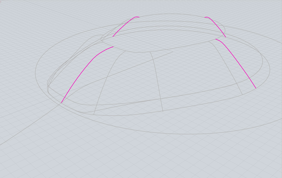
Starting out from production design drawings, getting the known profiles of the fore, aft, and port/starboard vertical edges, and creating them (shown in magenta) is pretty straight-forward:
Likewise the uppermost deflector grid ring:

…the saucer profile:

…and the seam outline (in a flat plan top view):

Taking the saucer profile—revolving it for form the saucer surface itself—then taking the seam outline and projecting it down onto the saucer profile gets you the seam in three dimensional space (again fairly straight-forward):

Now things get tricky.
Determining the key transition vertices points between the aft vertical slope path to the vertices for forward angled slope line (which is actually a 202.5º revolved shape for the front part of the superstructure)…

…was the deceptively hard thing to work out.
Because defining those transitional sloped vertices (the two highlighted in magenta below) not only need to keep the transition smooth between the start and end slopes (reprinted by the arrow in the image above) while matching what is seen in the photos of the exterior miniature…

…but critically slope inward and curve lateral in a way that from a surface…

…that can then be inwardly offset by the amount of alcove inset and the window thickness (the three “layers” shown below)…

…in such a way that interior curvature of that intersection meets at the interior window baseline (the yellow lines in the image above) all along the interior wall seam.
All this while doing so in a way that slopes upward to form the interior window plane properly to facilitate matching the interior shape and dimensions of the lounge miniature window dimensions. Which is again derived from projecting the window height rectangle (magenta) onto the interior sloped curved surface to form the window baseline and top edge (yellow shape)…

This can then be used to project up onto a plane intersecting with the column angles as defined in the Ekker top-view drawing to form the raw window shapes outlines (yellow)…

…which in turn are extruded to create shapes that intersect with the aft inner aft surface …

…to be cut out of the surface…

…which can then be “shelled” to form a shape with the thickness of the raw window framing. The corners of are then filleted to round the corners. The two windows on the right in the image below with their “corners” highlighted in yellow, have already had the filleting applied…

And so on.
It took over two months of tinkering to get it to match correctly in all those areas. It would be easy to simply ignore the interior wall and window baseline of the interior, and get something that looked pretty close to just the exterior. Many of the 3D models I have seen others make also don’t have the very subtle vertical bowing of the front and aft profiles, and simply make them a straight angle instead.
Where things don’t match perfectly to the interior drawings are the top view in the Ekker drawing. The windows are not quite a “long” from bottom to top (when viewed from above) as what is in the interior “set” miniature drawing.
Here however the Ekker drawing is not constant with itself in that the aft elevation window height doesn’t reconcile with itself to the top view window heights given the slope shown in the cross-section side elevation in the same set of three orthographic views in the Ekker drawing.
But the 3D model does match vertically in height to the interior aft elevation drawing, and match to the shape, size, and position to the exterior miniature reference images.
So that’s what I went with since it was the best solve.
I did however use the horizontal radius of the ellipsis in the top view drawing to determine the circular radius of the rounding (filleting) of the window corners. Which when “cut through” the sloping aft wall do pretty much match the shape when viewed directly from above as well as from the back/front (i.e. exterior view/interior view looking out).
I used the window lines of the top view Ekker drawing (which have centerline dimensions outward) to define the angles of the columns and the convergent origin point. Which was crucial to use it in working out the two key transition slope vertices for the outer shell and forming the overall proper outer superstructure base surface.
At first blush you would think it would not be too hard to model it.
But when you start trying to get down the millimeter (in-universe) and try and get it to all to line up and make sense, while still matching the exterior miniature forms, it is harder than you might expect. But to get it to reconcile with the interior miniature, and do so in a way that is faithful to what can be gleaned for the productions drawings (which have some internal inconsistencies in them) and from the photo analysis of the exterior, was a really complex undertaking.
The next big hurdle will be working out the spaces that factor in and accommodate the 8 round, and 2 elongated portals in the mid 2-3 deck window alcove inset of the superstructure.
This will help inform the spacing of the structural ribs, stringers, and so on.
Of course going to the Las Vegas for the Star Trek Creations Convention next week will delay that. But progress is being made.

The links do not work any longer. Can they be redone?
LikeLike
Thanks for the heads up. The images I originally posted over at The Fleet Workshop. They changed the privacy settings there a couple of months ago, and it obviously broke the links to the images. I re-uploaded them here, and re-linked them.
LikeLike
Thanks
LikeLike