
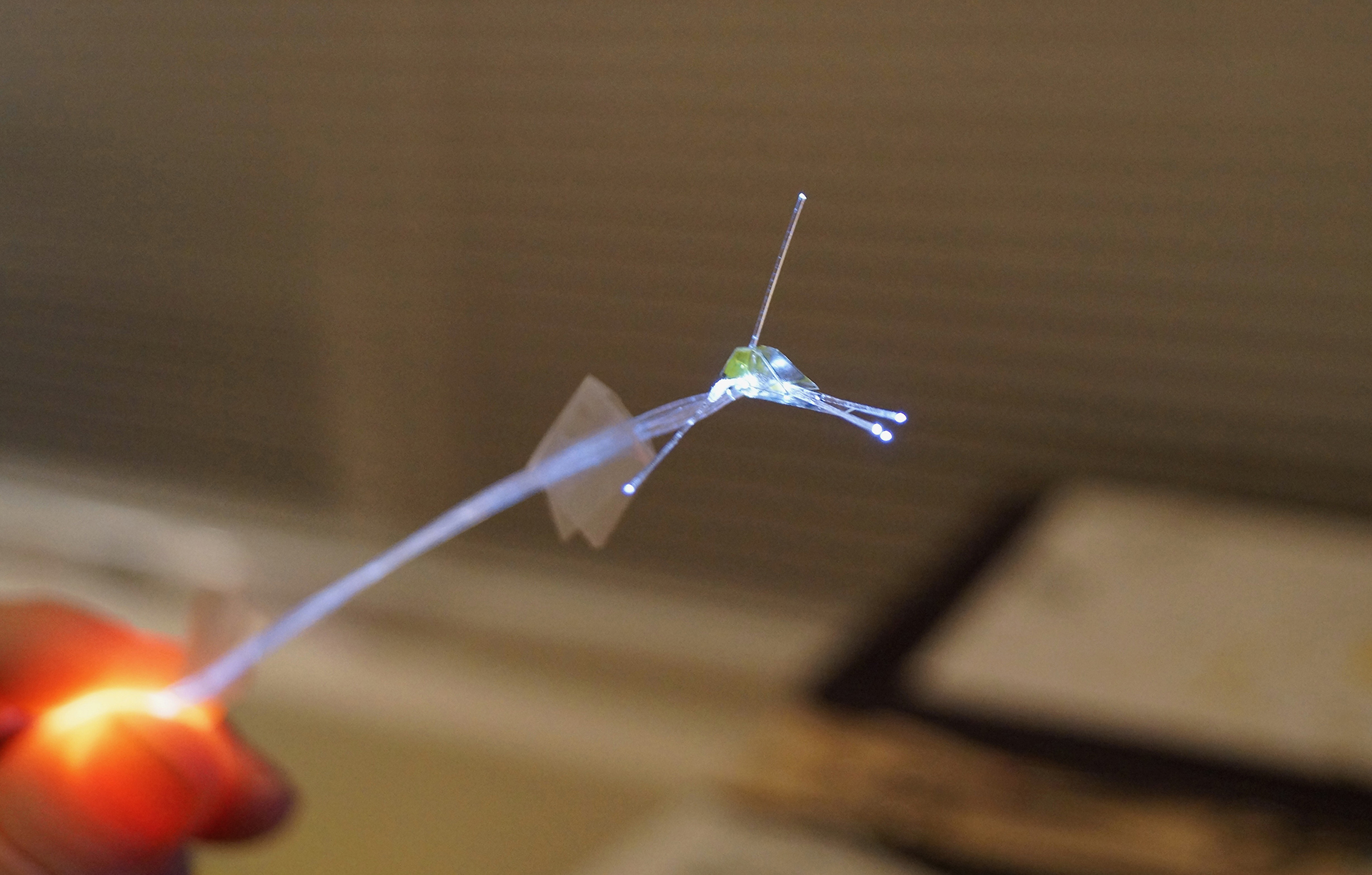
Tonight I assembled a decent transparency layer, and tested out threading six 0.25mm fiber optic filaments into the workbee. It was on the whole successful, though one of the side running light filaments moved while I was curing the UV adhesive, and it snapped inside the upper shell.
I need to improve how I flow the Lazerbond UV cured polymer adhesive into the small opening and figure out a more controllable way to keep the filaments in place while glueing and curing. The small mid-waist notch I put into the side panel worked for the most part, but in all the manhandling putting the Lazerbond into the small baseplate hole, one of them slipped out and subsequently got snagged and snapped.
Test threading of fiber optic filaments.
But as you can see in the photos, five out of the six were in the right positions once it was all said and done. These would of course be clipped pretty much flush to the upper hull, once the PVC “wrap” panels would be attached.
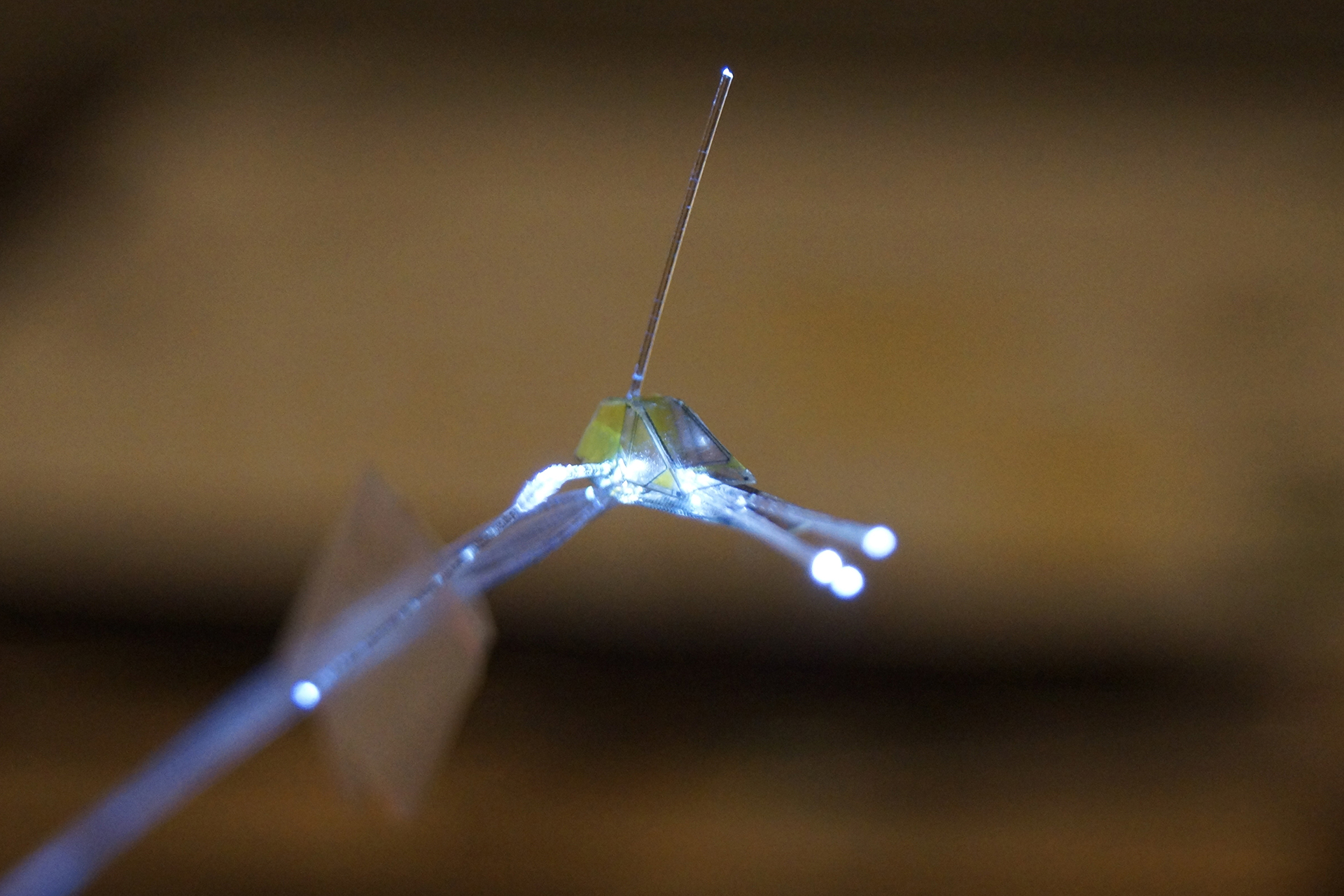
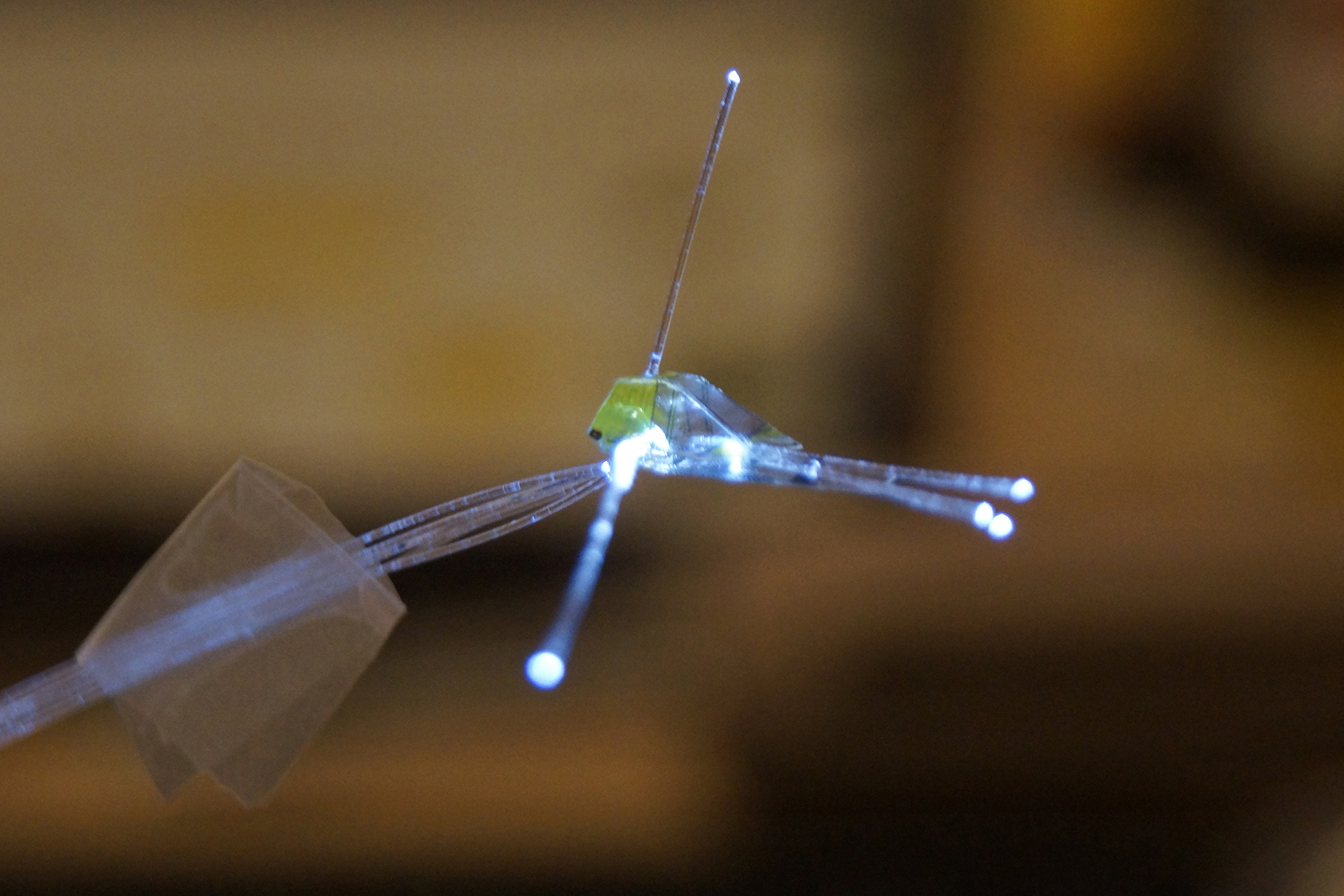
The side port and starboard running lights, while only test lit with the same single bought white LED, would be lit with the appropriately colored LEDs, red and green respectively. And as mentioned, once the workbee was fully assembled, clipped pretty much flush with the hull surface. At this scale just cutting them as close to the surface will make them stick out as much (if not slightly more) than the fairly shallow housing of the lights on the actual workbee.
The interior cabin is lit by the one snapped
running light fiber optic filament.
The one on the top would be lit with a yellow LED, and wired into the lighting control board that would make it fire off as a strobe. This one is actually already turning out to be both a challenge, but also a boon to assembly. Since the yellow PVC tape top panel has a prepunch 0.25mm hole in the vinyl, threading the filament through the hole actually makes it easy to guide the panel down into the correct position on the top roof face of the clear transparency build. It also keeps it from slipping around as the piece if held with fingers, etc.
In addition, the top/aft “spine” assembly has the same hole in it, so threading it down over the filament will likewise be useful to alignment and positioning.

SketchUp 3D model showing “spine” assembly in grey.
I also began drawing up the clear transparency piece artwork for the aforementioned “spine” piece. Because of the scale of it, I have had to simply much of it. So it won’t have the bevel faces on it though I may see if a light sanding on the edges of the key faces of the piece before assembly might simulate it.
It is the grey piece running up the starboard aft face and wrapping around on top of the roof that you can see in the screenshot of the SketchUp model to the right.
As you can see in the 3D model you can clearly see the amber colored navigational strobe which sticks out rather predominately above that piece pretty much at its front edge.
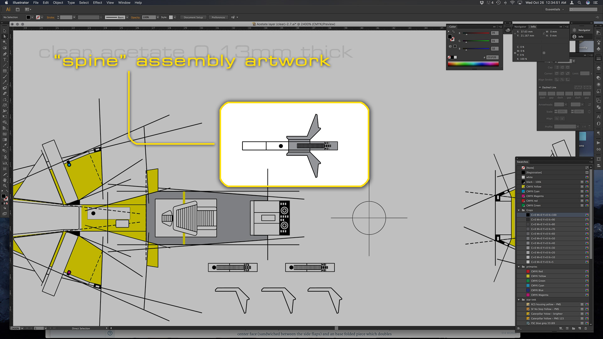
Initial rough artwork for assembling
the “spine” assembly.
It will be composed of one basic piece, which folds around on itself to form the two sides, the top center face (sandwiched between the side flaps) and an base folded piece which doubles back under the top face, and forms the face that mounts flush against the roof and aft faces of the upper hull. As with the shapes, the details such as the grill, the aft greebles, etc. are all greatly simplified. I noticed too that I need to add in small rectangle and two circles to represent the power charge couplers.
I only drew up that artwork this evening here at home, so will need to run it off tomorrow after work to see if I am close and test if that is “build-able”.
