
It’s been several weeks since my last post and a lot of experimenting and a possible change in direction is in the offing.

In the week leading up to Halloween, Michele’s co-worker, Shane, had offered to try and print up some test files of the workbee upper half on his Lulzbotz Taz 6 3D printer 3D printer. While the concept of 3D printing might be the solution to several of the fabrication challenges, particularly the workbee “spine”, the reality is that Shane’s printer and not having done micro printing on his printer, yielded less than usable results.
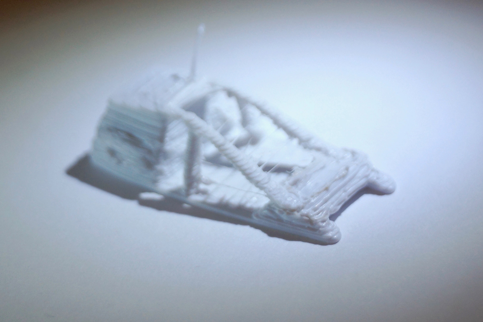
Workbee frame print at Shane’s not working out yet.
Even when the initial rough electronic 3D model file I had done was scaled up to a length axis dimension of 27 mm, which is 10x bigger than the 1:350 scale one, the results were not that good.
The issue of “oozing” and overheating of the layer was problematic. That issue might be possibly be overcome by using tricks such as printing two workbee shells at the same time.
This would allow an extruded layer to cool down on the first bee while the extruder was laying down that same layer on the second workbee before returning to the first bee’s second layer.
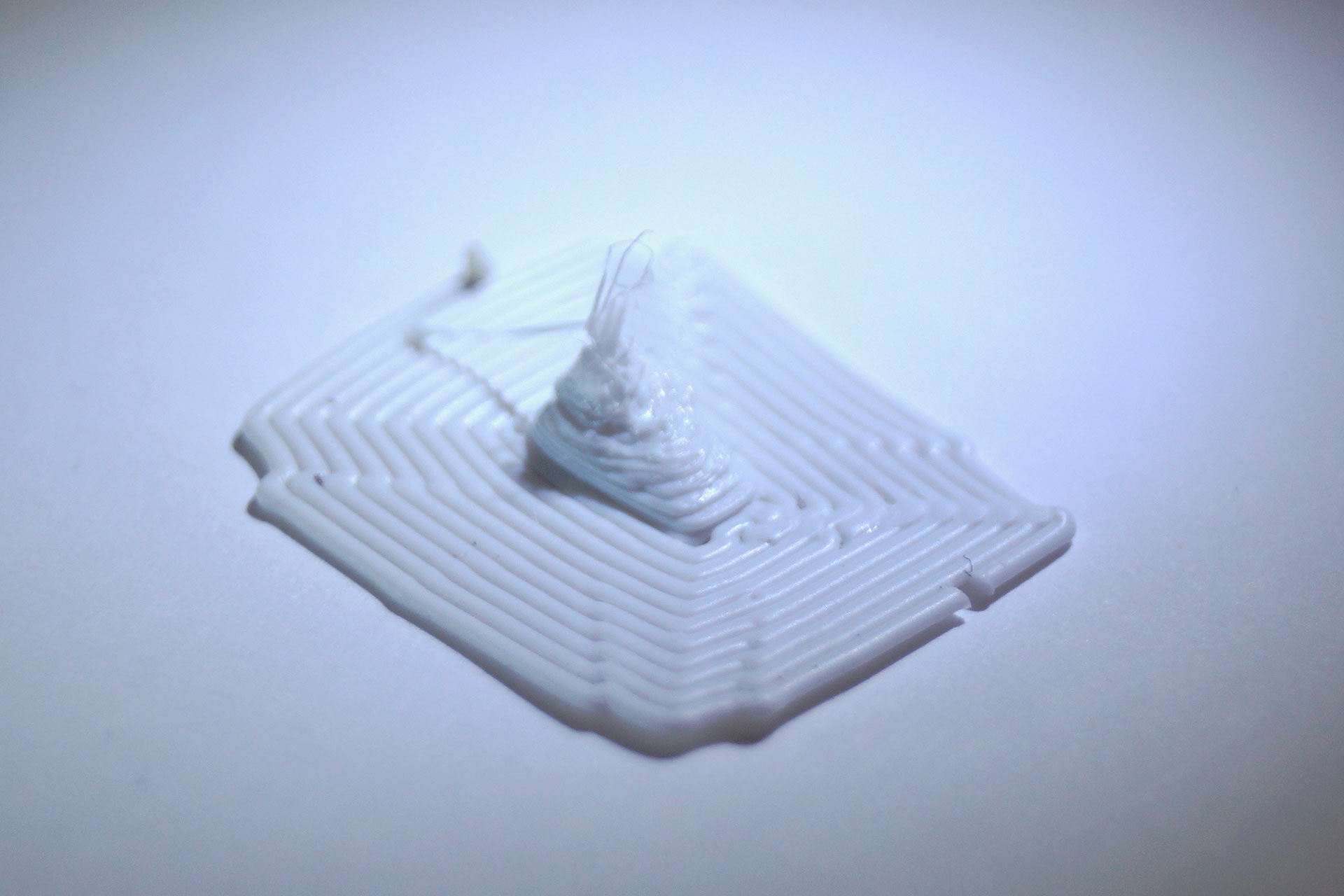
At scale it’s even worse.
But even if we overcame that, the extruder nozzle that Shane’s printer has is a 0.35 mm nozzle. So the extruded hot plastic basically comes out in too big of a “string” of plastic. As an example, the vertical window column of the workbee at the 1:350 scale is 0.102 mm wide.
But while researching what level of micro scale printing can be achieved, and also working up various 3D models to “cheat” the design, I also happened upon a website called Shapeways.
Shapeways is one of several 3D printing service that allow you to upload a 3D model, and they will produce it on high-end 3D printers in a very precise and controlled production facility. They can do this at very reasonable prices because they gang up multiple client models into a larger “mega model” or block of models and run it all of at once. Then they separate the various client pieces and finishing them off, inspect, then ship them.
They can produce the prints in various materials and at a level of small detail that might be doable. While I still would need to work up some revised 3D model files, it might be the solution I was looking for. This can still possibly be done in tandem as a hybrid of the printed acetate, and/or PVC tape as well. But we shall see.
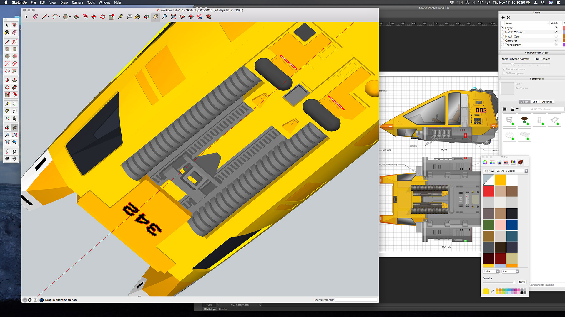
When working up viable print models to first test on Shane’s printer, and then digging into what Shapeways does, and test uploading some 3D models, I still need to do some more serious 3d modeling work. This in turn lead me into a crash course in actual 3D modeling software beyond SketchUp which I had been using for basic modeling up till now. Mainly because it was free.
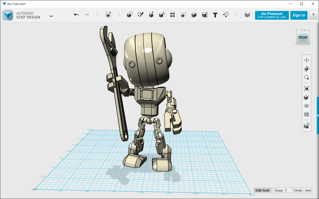
123D Design 3D modeling application from Autodesk.
I then started trying out 123D Design from Autodesk, which is also a free download app.
When working up those initial 3D models to try and test printer at Shane’s, and then to get a model that would pass Shapeways auto checking for wall thickness, etc. I realized that I need to rebuild the 3D models up from scratch instead of using some of the SketchUp, workbee models some had created that I was using as a base model to modify and work from.

David Kimble’s 1978 Workbee Blueprints (sheet 1).
This also forced me to go back into another deep dive into the original source materials. This includes photos of the filming model (which are very scarce) and the “official” blueprints when Star Trek: The Motion Picture first came out in 1978 which were drawn up by David Kimble.
While Kimble’s drawings were very well done, they are not perfectly detailed, and more critically, they don’t include a back or bottom view in the orthographic drawings for the workbee. It only shows the back in a second sheet which are views of the manipulator arm attachment sled to the workbee, which are shown in various small shots flying around the Enterprise in the movie while it was in drydock, as well as the “cargo pod train” sled assembly.

David Kimble’s 1978 Workbee Blueprints (sheet 2).
But because that second sheet is focusing on that auxiliary attachment gear to the workbee and not the workbee itself, the aft view the workbee is just a rudimentary outline of the hull shape, aft viewport hatch, and outline of the spine assembly.
There are no canon source illustrations or photos that I have found for the underside. Various fan created “blueprints” simply extrapolate from the top, side and front views which are shown int he Kimble drawings, what little can be spotted in screen captures, etc. and basic guessing.
Erroneous lower windows and “coil” assembly.
I have spotted several erroneous assumptions that have entered into the fan canon over the years in various schematics, 3D models, rendering, etc. For example, the lower windows near the pilots feet are shown in most bottom views and 3D models as only existing on the sides of the lower hull. When in fact it is seen in a few frames from the movie that the windows actually wrap underneath onto the bottom floor of the bee’s hull.
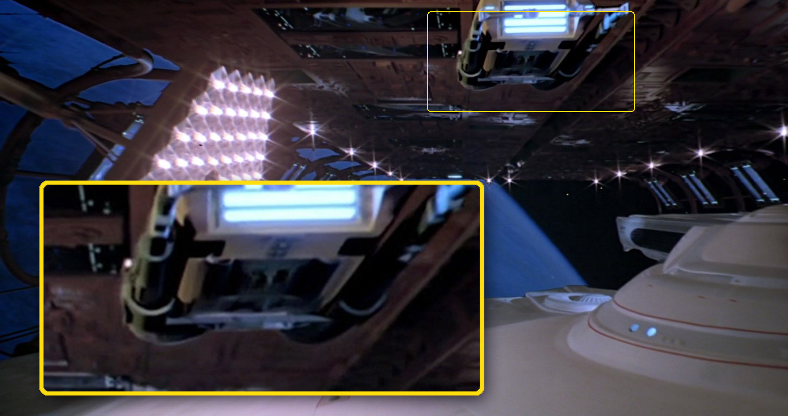
Frame from the movie showing the elusive lower windows.
Likewise there are two long dark cylinders that run along the underside of these. This is shown in the Kimble drawings. But in the side view it only shot four segments to these cylinders, and because of the shallow angle when illustrated in the front view, are drawn as several close semi-circles. Many people seem to have interpreted that to mean these are sort of pair of coils running back from front to aft ventrally on the underside. But that assumption seems to be in error as there is no canon photographic evidence of these cylinders being “coils” at all.
So I am going back to hose signal Kimble illustrations and correcting the orthographic drawings I have and creating a more precise and accurate set of 3D models.
This in turn lead me to try out the various free 3D applications, and seeing what I could do to recreate a more accurate set of orthographic illustrations as well (which are used as a basis on upon which to build the 3D models).
The upshot is, most of the poly-mesh 3D modeling software can’t accurate create the 3D shape file I need because of the vary complex subtle compound curved surfaces that make up the hull.

Moment of Inspiration 3D modeling software.
But I did find a 3D modeling application, Moment of Inspiration, that available on both the Windows and Mac platform. It had a free trial version (where saving or exporting files is disabled) and it does have a tool called “network” that produces a “loft” between two compound curves in all three axis directions. Not only that but it can import and export native Adobe Illustrator files. That is huge as I am intimately familiar with, and use, Illustrator all the time. I have relied on it extensively in working up base drawings upon which to try and do some 3D modeling in SketchUp, 123D Design, etc.
So after spending a few evenings playing around with it, tonight I finally broke down and purchased that application. So for the next week or two I will be working up the 3D models of the hull parts, spine, etc. to then test by having Shapeways fabricate them.
Shapeways has a material they can print with they call “frosted ultra detail” (FUD) acrylic, which is a UV cured acrylic polymer. I would likely go with their slightly higher priced (but finer detail) version of FUD called “Frosted Extreme Detail”. I will gang up several of these bee hulls (once I build them correctly from the ground up in the new software) and have them printed in FUD and see what the translucent levels are at their min. wall thickness of 0.3 mm, its sandability, smoothness, etc.
Seeing how workable that material is, dipping them in acrylic varnishes such as Future, etc. to see if I can make them close enough to optically clear will also determine how I approach the 3D models for a final build and whether I still incorporate printed transparency film (with auto window tinting film on it) as the window “glass”. If that level of transparency does work it will determine whether that can be part of the printed models hulls themselves when made out of FUD and “polished” up enough to accommodate simply applying the auto tinting film to it… or not.
If it can’t that means the earlier some of the early 3D model designs (cleaned up and rebuilt) where the window holes are therein need to bar “filled in” by adhering printed transparency film will be tried.
Anyway, as it has been up to this point, progress. Progress in the form of one step forward, one step back, one step sideways, and a new possible step forward.
