
After purchasing the Moment of Inspiration (MoI) 3D Modeling software the other night, I have managed to make decent headway into finally getting a hyper-accurate outer shell for the workbee drawn up.
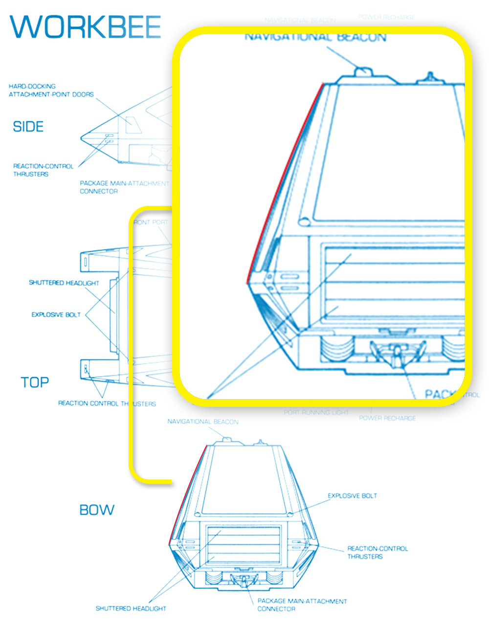
Curved profile of the workbee hull as shown
in David Kimble’s 1978 illustrations.
As I mentioned in the post the other night, the slightly outward bow to the upper shell makes is a very subtly complex compound curve. Simply lofting it, which most consumer end (particularly the free variety) 3D modeling software can do, would yield a curved surface that is only bowed in one axis. Basically a surface that would be like that of a section of a very large cone. Where if you looked at a line between two points along the vertical, or Z axis, it would be a straight line.
But as is shown in the David Kimble “official” blueprint illustrations done back in 1978, that front/rear profile of the outer edge show the hull is curved slightly outward as viewed from the mid-waist separation line, up to the roof line.
Thankfully MoI has a tool/command called “network” which creates a surface from a two-directional network of curves. The curves that make up the network form a kind of two-directional grid, similar to a fishing net, hence the name of the tool. A network surface is sort of like doing a loft in two directions simultaneously.
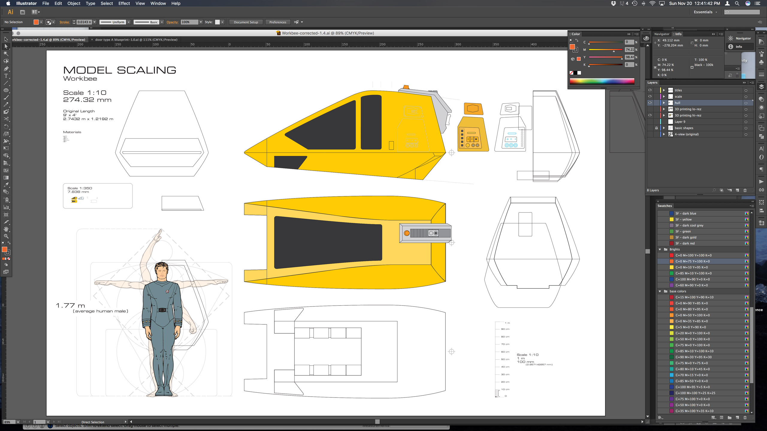
Illustrator drawings to generate the “ribs” for creating the correct outer hull shape.
Aside from numerous small errors in some of the fan-made 3D meshes and models, this is one of the larger errors I see all the time while scouring the web. But thanks to MoI and some serious reverse engineering from Kimble’s drawings in Adobe Illustrator, I was able to draw up accurate side section 2D “ribs”. These were done at key points along the hull. Specifically at the highest point in the curve of the roof, the aft face edge, and where the side of the hull is widest.
This along with the existing roofline when viewed from the side in Kimble’s drawings, allowed me to accurately derive the roof/side edge. In combination with the key “ribs” in place, this allowed me to run the network tool over it and “skin” the outer hull shape in the correct, subtlety outward bowed compound curves.

MoI generated hull shape using the “network” tool.
MoI is very comfortable for me to work in, as it allows direct cut and paste shapes from Illustrator into the MoI .3dm files. 3dm files are the native file format of the program, as well becoming a standard for the exchange of NURBS geometry. This means no re-tracing or loss of the mathematical purity of the vector-based Bézier curves which is what the other free 3D software applications I experimented with forced me to do. I can work in Illustrator like a fish swimming in water since I have been using that tool professionally for decades. Being able to directly utilize that work is a huge boon.
The other aspect that’s great about MoI is that it handles import and exporting a variety of file formats and 3D geometries well. So I can export the NURBS geometry I work up, to .obj files which polygon mesh-based programs such as SketchUp, work in.

Yes, Admiral Kirk is standing next to the
workbee hull in SketchUp.
Once it is in SketchUp, or Meshmixer (from Autodesk) or any of the other polygon-based “mesh” programs, I can then clean up and simplify any of the complex faceting that the conversion from mathematical curves into polygon geometries might introduce into the shape. I can then export it into a file that Shapeways, the 3D printing service I am looking to test out in the coming weeks, can use.
And yes, I am a big nerd at heart in that I also spent an hour last night taking one of the PR photos of William Shatner (aka Admiral Kirk in the movie) from Star Trek: The Motion Picture and created an “in scale” 2D “person”. These 2d people are ubiquitous in SketchUp models for visual scale purposes, so now I have Kirk standing next to my workbee hull. This seemed more apropos than using the generic “person” figure that is automatically included when you create a new SketchUp model.
While making these workbees at such a micro scale (1:350 scale) of the Enterprise model is in, having these files can pay off down he road as well. I can simply scale up and refine the level of detail in them in order to potentially 3D print up parts for my own scratch-built larger scale workbee. Having a fully detailed lit-up workbee at say 1:10 or maybe 1:16 scale might be a nice display companion with the Enterprise kit once it is built. If for no other reason that to be able to have a “hey this is a larger model of what those little micro yellow vehicles in the hanger bay are” …sort of thing.

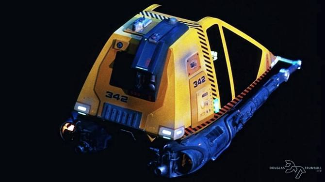
Aft image of the workbee that Shawn Donovan pulled from
Doug Trumbull’s website.
Thanks to Shawn Donovan over at the Star Trek The Motion Picture Appreciation Society on Facebook (yes that’s really a thing) he managed to send me a photo he culled from special effects genius, Doug Trumbull’s old website. A much needed, relatively usable, aft photo of the workbee. So I will be correcting and improving on the orthographic drawings I have been making, for the “spine” assembly. Then porting those over into MoI and adding it to the 3D model.
Hopefully before Michele and I head to her father’s place for Thanksgiving, I will have a 3D model uploaded to Shapeways that is worth spending the $10 or so to have a test 3D print run up.
That will be the real test. Being able to see how this level of detail holds up and what the workability of the “frosted ultra detail” (FUD) acrylic material is will be crucial. Particularly if it can be chemically and/or with sanding and buffing be made reasonably clear and transparent. If that can be done it will inform how and if I will need to fabricate the windows (or not). If they can be directly included into the 3D print, that will of course have a big impact how I model the final shape(s) and pieces.
With any luck and with some extra finishing work to get it “optically” clear enough to pass as tinted “glass” for the windows (that’s transparent aluminum to you 21st century luddites) the frosted translucency of the material should help in lighting up the headlamps from behind with the pair of fiber optic filaments.
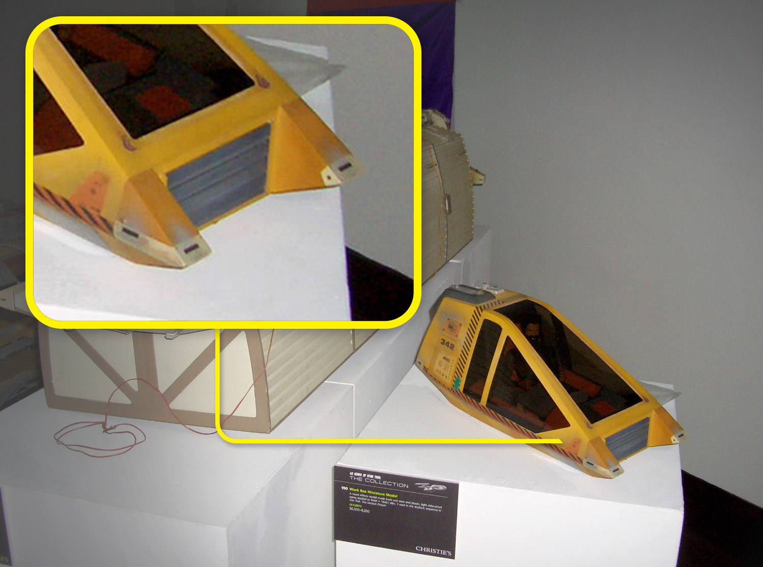
Reaction Control System detail which may
be able to be lit after all.
If that translucency holds up, that means I could potentially light up the micro reaction control system (RCS) thrusters which are in all the corners of the workbee. It would also allow me to potentially get smaller and more accurately shaped port/starboard colored running light as well. The 0.25mm fiber optic filament is actually about 30% too big and is round. Having the small square running light shape as an embossed detail extrusion on the outer panel/hull, and backlighting it with the fiber optic filament, would make it much easier and better looking as well as more accurate.
But I am getting ahead of myself. Need to keep plugging away on the 3D model and see what the next set of challenges/solutions are once I get to running up some actual 3D test prints.
