
A big step forward last night and today. After working on some test 3D models to do some 3D printing for the workbee parts, I uploaded the initial upper hull piece to Shapeways, and it is now in production.


3D model accepted after uploading to Shapeways.
As mentioned in the previous post, I was intending to have Shapeways, a commercial 3D printing service, run up some test workbee pieces. This is to mainly see what level of detail is “printable” and how said detail holds up to post-printing finishing.
After a few weeks of working on the 3D model base artwork and model files, uploading it and having it fail the automated model testing the system at Shapeways runs everything through before they even look at it… success!
The model passed both the automated checks, as well as being passed after they manually reviewed the design file to make sure it met all the minimum and maximum specifications for printing it up in the material requested.
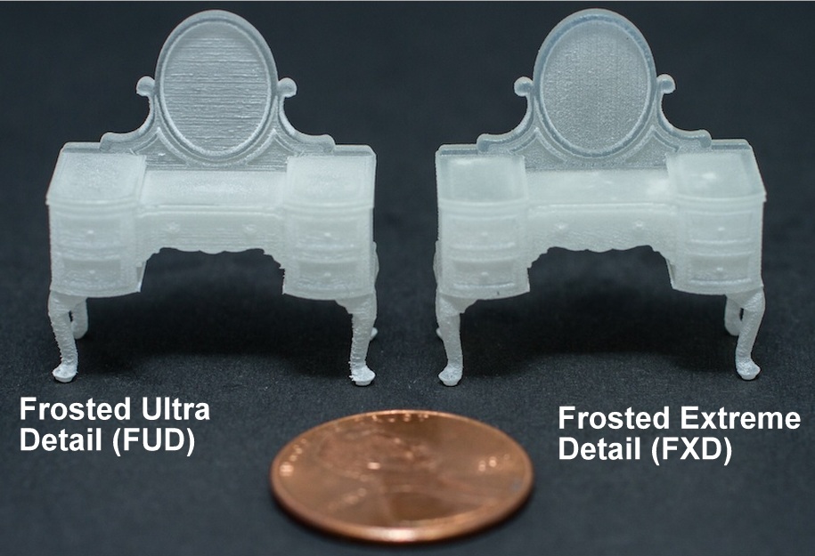
Close-up image of FUD and FXD materials, showing the
texture inherent in the printing process.
I went ahead and ordered two of the pieces to actually be run up in “Frosted Ultra Detail” (FUD) UV acrylic material. I actually went with they slightly more expensive version of FUD called “Frosted Extreme Detail” (FXD) material. This has a slightly smoother finish and according to their website, the material that offers the highest level of detail. I ordered two so I have a couple of pieces to work with in testing the finishing techniques, etc.
As with all 3D printing, there is some layering texture in pieces that are 3D printed. This is inherent in the technology of 3D printing as it is done by “printing” the material in micro “slices” which builds it up layer after layer. Think of it as a sort of extreme version of how architectural models simulate ground contours with built up layers of topographical contour lines.

Embossed windows in the 3D model shown in MoI.
In the model I uploaded last night I made the windows raised the min. level of detail embossing that Shapeways design guidelines allow, 0.1 mm.
My thinking on this is that with the window surfaces themselves being embossed (i.e. raised) I will be able to test sanding and then polishing and buffing them to see if I can get them to an acceptable level of optical clarity.
The same approach I intend to try with the raised port and starboard running light fixtures. As mentioned in last night’s post, I hope that the frosted translucency of the material itself will allow for enough light conductance with having a fiber optic filament glued to the backside. This would make it so I would not have to have holes for the running lights in the hull itself. The scale and shape issue not having to use the raw fiber optic strand itself would help improve the accuracy of the model.

Embossed running light(s) shape I hope to back-light.
If that works, I would be able to consider back-lighting the RCS thrusters as it is in the actual filming model, which are way to small to even contemplate using an actual fiber optic filament individually. My hope is that simply lighting up the entire corner from behind, then putting on thick enough coat of opaque base coat paint, and then hull color would make it so that scratching micro “holes” in the paint layers would allow the light shine through.
Aside from the transparency and translucency testing, the raised windows and running lights will also hopefully aid in masking for painting the hull color. Particularly the problematic window A and B pillars. This was the main issue I had when doing some of my early attempts at printing these pieces up on flat transparency film and then folding the parts in a manner similar to micro-origami.
The problem then was that the layer of paint itself was almost as thick as the window column widths themselves. Between that and the scoring and folding, the paint would either lift off after removing the frisket or flake off when the transparency film was stressed and flexed in the folding process.
Since there now will be no “folding” involved in these 3D printed pieces, the flexing issue will not be there. In addition, the raised windows should hopefully allow for a break line between the masking frisket and the hull surface I want the paint to stick to. The rougher texture inherent in the frosted plastic, in addition to the micro texture from the 3D printing process itself, should help the paint adhere to the lower hull surface in a way that when lifting off the frisket, it should “break” cleanly. Of course we shall see when I get the pieces in hand. It all works great in my head, as do most things. (wry grin)
The other painting test I hope to try out with these pieces is the side “life-support equipment access panels” towards the back of the hull. Again, seeing what level of detail is produced is the first thing I will be looking at. As all the embossed and debossed greebles are at the minimum threshold that Shapeways design guidelines allow when printing in this material. But the painting aspect of these panel details is to test out some ideas I have in how to get such micro-detailing painted.

Debossed panel detailing for paint testing.
For example, the five square shapes that are vertical on the panel are actually just painted details that are for the most part flush with the panel in the actual filming model, which is nearly two feet long (as opposed to 7.62 mm in 1:350 scale). So I have those five squares as debossed shapes.
My thinking is to airbrush the overall panel color with a fairly thick coat of paint. Then using a syringe with a fairly healthy needle aperture (the upsides to living with a nurse) to shoot some micro droplets of black (or dark grey) paint to fill those tiny square depressions. Doing it multiple times if need be until I have built up a pool of paint that when dried is pretty much even or flush with the thick panel color layer paint. Even if the black pools of paint bead up and are bulbous due to the surface tension of the paint after drying that’s ok. In fact that is what I am hoping to achieve. Then I would use some micro-sanding sticks and sand down the top layer(s) of the thick built up paint, making the two different color paint layers flush with each other.

Peppermint hard-candy with stripes made by smoothed blended layers cut perpendicular to the layers.
The hope is that the now even and smooth surface would be solid yellow except where the black, square shaped pools of paint were which would then be a flat, flush black square of paint. Sort of like how the swirled line patterns in peppermint hard candy is made of layers that are made flush on the outside when the candy is sliced perpendicular to the multi-color layers twisted together when they make the candy.
Again, all great in theory. But we shall see when I get the parts in hand.
But I am excited to have something finally moving forward into a test fabrication at Shapeways, which is slated to be produced and ship to me on December 7th.

Pingback: Things are Taking Shape(ways) | Third Wave Design