
Well back in December I had a motherboard and drive issue with my iMac, and after that, was my son coming home for the holiday, then I took a slight break from the workbee while I still try and get better reference material for the aft view of it as well as the enigmatic bottom view.

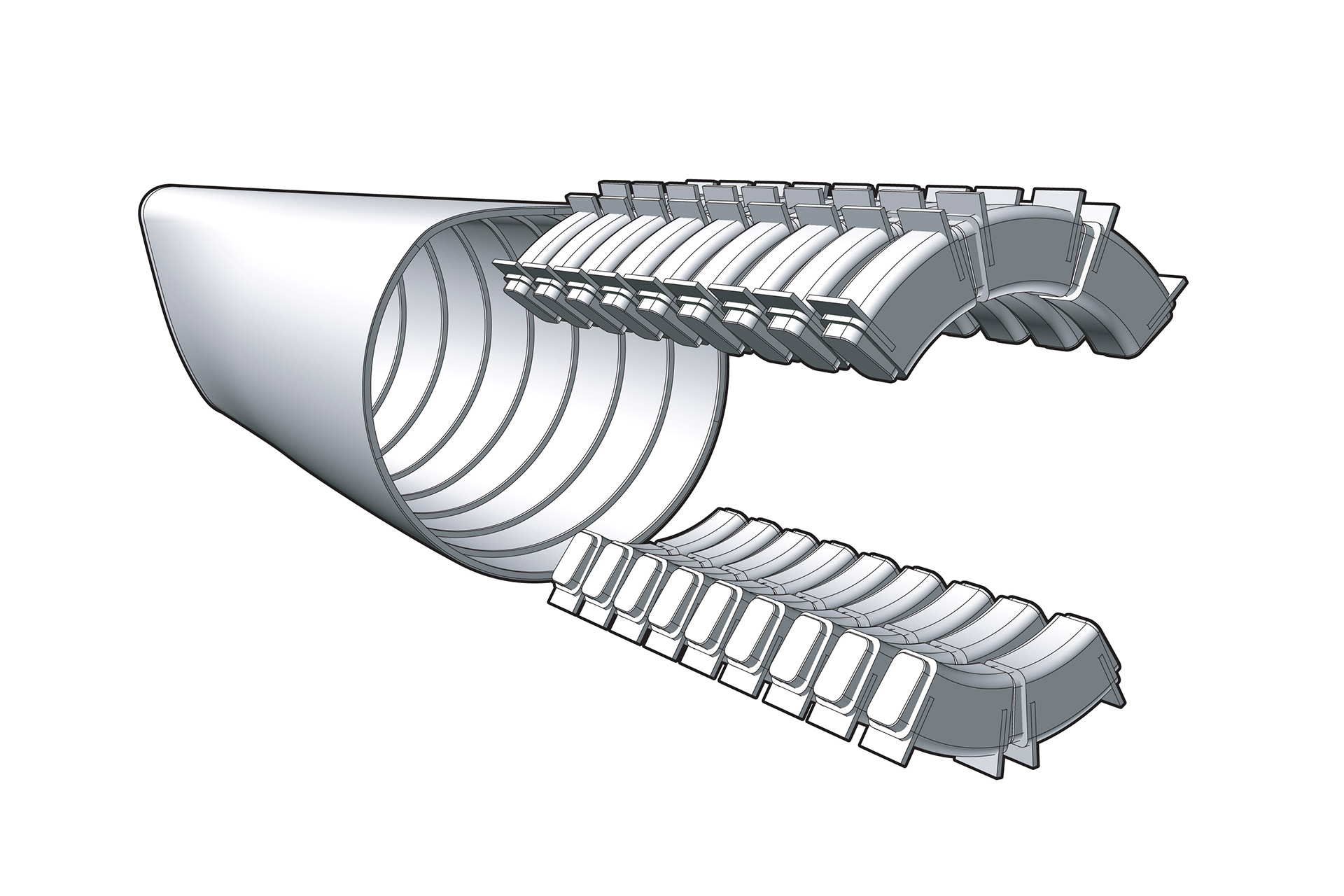
Preliminary aft internal rib structure and warp coil arrangement of the Enterprise warp engines.
While taking a break from the workbee stuff I have struck up a conversation with a guy on Facebook who is collaborating with another person on making detailed blueprints of a Star Trek: The Motion Picture (ST:TMP) “refit” era treatment of the Federation-class dreadnought.
That work is focusing on modifying the third engine nacelle from the standard port/starboard iterations of the warp engines to a center one, and I volunteered to help in that endeavor. This will involve reconfiguring the warp side grill (the part that glows blue/violet internally) and the flux chiller grill side (which does not light up internally) so it shares both types of functions on both sides in order to make it symmetrical.
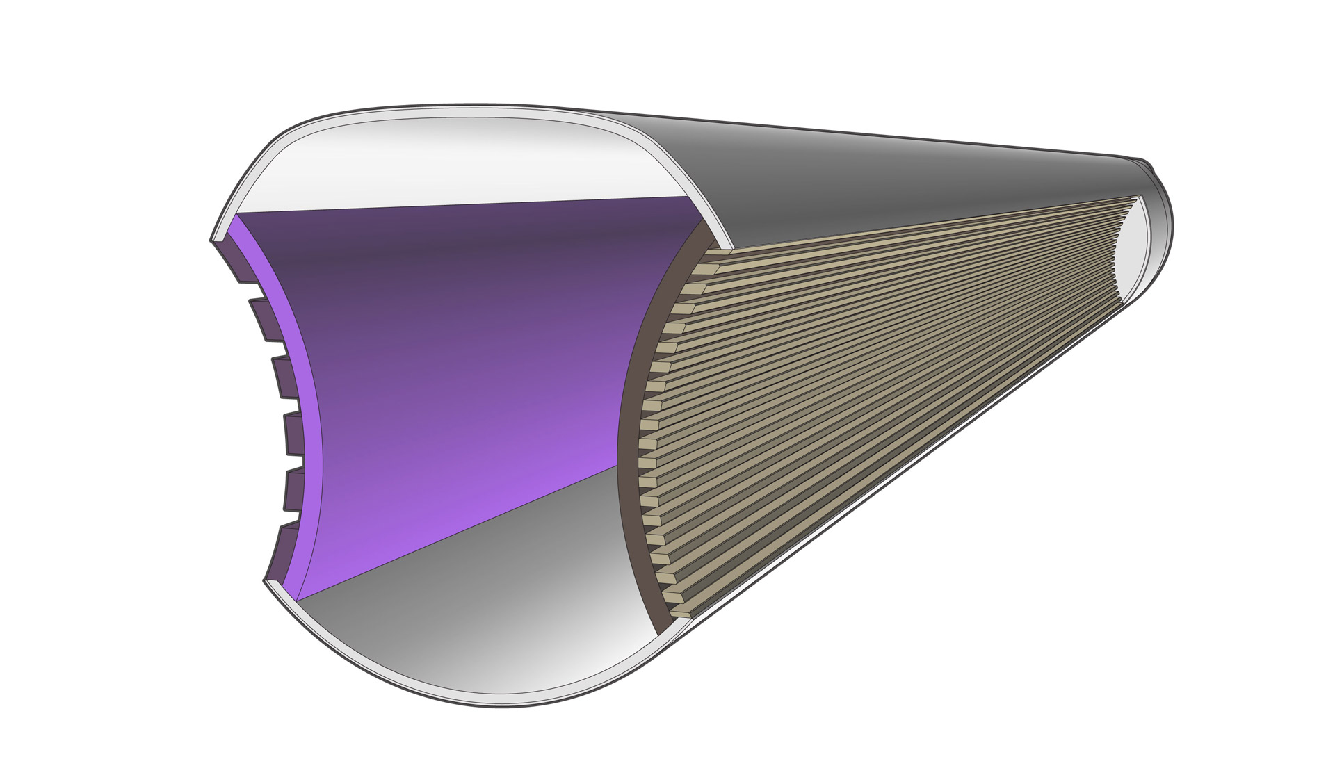
Preliminary start to a 3D model of the warp engine body.
This is something that has always bothered me (and the guys I am working with on this project) when it came to fan-made starship designs which have an odd number of warp engines.
Whether it is single nacelle designs such as many of the destroyer and scout class ships, as well as heavier class ships like the dreadnought and carrier class vessels which have third “center” nacelle. It is simply “wrong” from a deign standpoint to have an asymmetrical warp engine, which all the “refit” era vessels have. This also helps to reconcile one of Star Trek creator Gene Roddenberry‘s “laws” about starship warp engine design which states that warp engines always need to operate in pairs.

Preliminary aft internal rib structure layout 2D work-up. It also shows hull thickness and composition cross-sections.
At least for this three nacelle configuration, since the center warp engine would function as a “paired” warp engine with both outer warp engines, this will sort of square that circle. Though of course that doesn’t address all those single-warp nacelle designs that have been floating around for decades.
It is also worth noting that this pairs-only “law” from Roddenberry was actually violated in canon with Star Trek: The Next Generation (ST:TNG) episodes such as All Good Things… which shows a future variant of the Enterprise-D which a third nacelle configuration similar to the Federation-class dreadnought.
So I began making a detailed base 3D software model of the Enterprise-refit nacelles to use as a starting point. I then spent a couple of weeks pouring over that reference material to work out the theorized underlying rib structure to accommodate the external paneling markings and so forth.

The Kamokuna lava outflow from Kīlauea’s Puʻu ʻŌʻō vent shooting into the ocean as the sun begins to rise.
However at the end of January my better half and I went on a two week vacation to Hawaii`i which was a great get-away. We spent 4 days on the “big island” of Hawai`i and the rest on Maui,
We experienced some real bucket-list experiences of both whale watching and viewing the current lava flows from Kīlauea the most active volcano on Earth, pouring into the ocean as the sun was coming up. Truly jaw-dropping to see and an unforgettable experience.
Anyway, this is the first weekend since all that where I have had the chance to start getting back into the aforementioned work on both the warp engine nacelle drawings and the workbee drawings.
About the latter, I was doing another Google search on the workbee, this time not an image search but rather a text search and happened upon a website sciencefictionarchives.com It is a company that has a pretty impressive science fiction prop, custom and model collection which they have for hire for events/exhibitions. They seem to be the people who purchased the original workbee filming miniature from the Christie’s auction back in 2006.
The rub of course is that its French company and so it seems most of the exhibitions they get hired out to display some of their collection are all in Europe, which precludes any realistic chance of me every coordinating attending any exhibition which might be open tot he public unless they somehow do one in the U.S. and is close enough to make it practical for me to even attempt attending something like that.

View of the warp conduit “blow-out” panels on the original filming miniature.
I sent them an email to inquire if they had high-resolution photos that they would be willing to make available (even for purchase) of the miniature, but as I sent it in the wee hours of Saturday morning in France, I don’t expect a reply until possible Monday (if at all). If only someone in Europe had the motivation and means to attend an exhibit they might be putting on there in Europe and snap some image on my behalf (assuming the people at sciencefictionarchives.com are not willing to provide good images for sale) but at least I have a little more knowledge of where the model now resides.
Anyway, I hope to break out my Dremel tool and polishing wheel bit and experiment on further polishing/smoothing the frosted ultra detail acrylic 3D test prints of the workbee upper hull piece I had shapeways.com run up for me awhile back, and them do some more drawing work on the Enterprise nacelles a bit more.

The warp engine magnatomic amplification crystal.
On that front, before I went on vacation I was looking anew at the the swept back pylons of the refit, and where the blow-out panels are and where it is assumed that the warp plasma conduit would be within said pylon (coming up from the engineering room area we see at the aft end of the ST:TMP engineering room set in the movie). And putting thought into that assumption and the location of where the magnatomic amplification crystal is (the little blue-lighted dome at the top forward area of the nacelle) and it struck me as very odd, and not very well justified positions in relation to each other.
Going back to the iconic David Kimble’s 1979 cutaway poster from ST:TMP which shows some of the engine insides in its cutaway views (which are all technically non-cannon but given the providence of that work, can be taken as petty solid) didn’t really help matters that much either. I had been working up other ideas about the actual structure of the warp coils themselves which are more in line with the later evolution of the warp engine coils as shown in the ST:TNG episode Eye of the Beholder, which established the foundation of subsequent Enterprise-D blueprints and drawings of what the inside of warp engines look like.
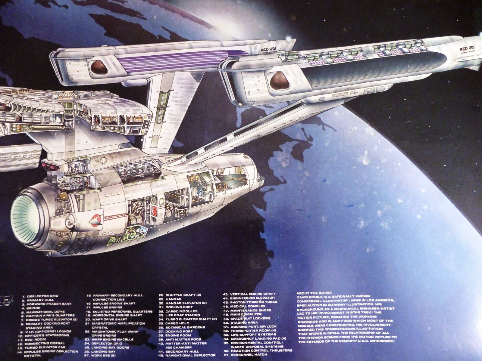
Engineering areas of the Enterprise cutaway poster.
Don’t get me wrong, I think the swept back pylons are one of the better design/visual aesthetic improvements made to the refit Enterprise vs. the the original series Constitution class version and most subsequent variants of Federation vessels. But I am still trying to work out a plasma conduit/warp coil/amplification crystal arrangement (internally) which “makes sense”. I am currently still in a rough “no idea is bad” exploration on a justification on why the crystal is located where it is in relation with where the warp plasma comes up through the pylon into the nacelle (basically mid nacelle fore-to-aft).
If anyone has any rough ideas, I would be more than happy to hear them and consider using them.

Pingback: Getting Back To It – Third Wave Design