
Going back over my Workbee 3D files to pick up where I left off, I thought all was good and would begin detailing the underside of the vehicle. But when I began looking closely at the reference images for the original filming miniature I noticed a major problem.

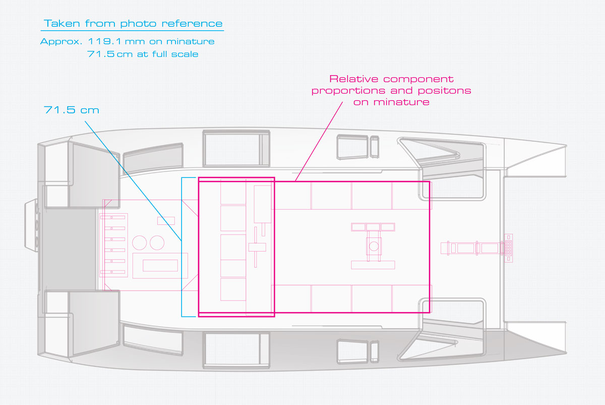
I began roughing out the block dimensions of some of the underside components in Adobe Illustrator. I used a known dimension of one of the components on the underside of the filming miniature which I had a reference image with a ruler scale next to it in the photo. That component was approximately 119.1 mm on the actual filming miniature.
However when I scaled it up along with the other roughly traced underside components, I noticed the proportions where not fitting properly within the bottom face of the chassis. This is shown in the screen capture below, overload atop the 3D chassis I had previously constructed.
The original bottom face was determined by building the aft engine insets which cut into the main chassis based on the original “blueprint” drawings done by David Kimble back in 1979.
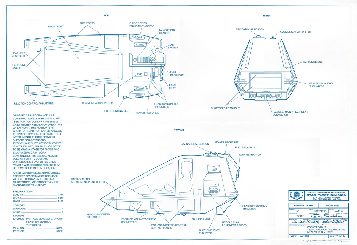
However what was drawn by Kimble never seemed to make sense just looking at the profile portion of the drawing. Complicating the matter further was the lack up a bottom and aft view drawings.
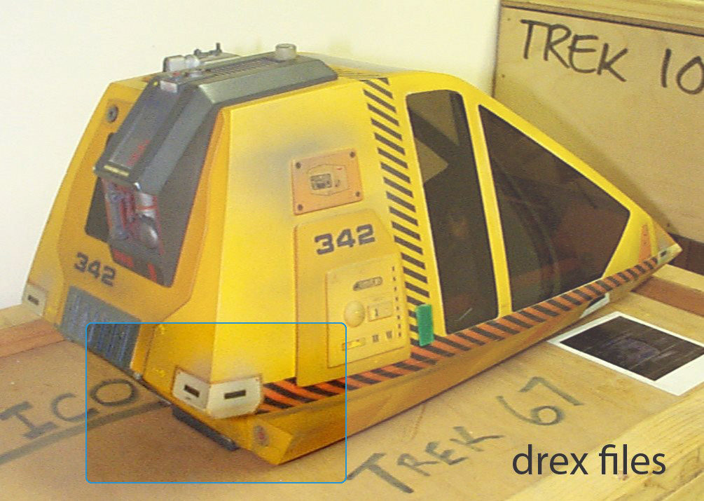
But in recent years, I had come into possession of some good quality reference images taken of the underside and aft views of the original filming miniature. In looking at the actual bottom face, and some contextual hints in some of the other images of the filing miniature taken by Doug Drexler back in the 1990s like the one below, it’s clear that the inset cuts into the chassis for the aft main-thrusters is not accurate.
In the cleaned-up profile drawing below, you can see the problem area in the erroneous extension of the bottom center section in the Kimble drawing.

This problem stems from the way the aft center pylon was drawn, from the lowest point in the aft portion of the chassis frame, up to where the aft corner RCS thruster modules are located. This in turn caused an inaccurate rendering of engine recessed alcoves. The angle and depth are not correct and introduced a host of problems for creating an accurate underside of the workbee.
When initial building the 3D model based on the Kimble drawing, this resulted the bottom flat face is too short front-to-back and an errant “T” shaped extension of the bottom face of the chassis when viewed upward looking at the bottom face. You can see this in the image of bottom view of the chassis below, which I have highlighted with a magenta line.

This is not accurate to how the shape of the bottom face is on the actual filming miniature. This is what caused problems when I was trying to get the various detailing components roughed in. Because the back edge of the bottom face was shifted too far forward it caused the various components overlaid on the underside to be both too long and shifted too far forward, and would cover the floor windows and hang of the front of the vehicle.
So in short, when drown in proportion to each other, the components were simply not fitting.
In the actual filming miniature, the lower aft center pylon comes in at at angle and meet the vertical main-thruster ports. That forms a single angled edge, and the alcove is much shorter. You can see this in the detail from a reference image of the underside of the original filming miniature shown below.

Notice that the aft center pylon comes down at an angle and meets up with the flat bottom face of the chassis what is basically an angled edge (when viewed from the side).
Spotting this however meant that the entire chassis component had to be re-worked with the new shorter angle for the main-thruster alcoves. The upper portion of the chassis that I had built it was still accurate and I absolutely didn’t want to alter the outer faces at all. I particularly did not wish to alter in any way the side rear panel face areas where a huge amount of effort was made to fully detail all the port and starboard side access panel components and “greebles” like those shown below.

So to create the new chassis piece, I used the basic “frame” spline segments I had already worked out for making the outer body surface. But I would need to rework the side-profile shapes for the main-thruster alcoves in order to create a new correct chassis shape. This would solve the size and shape issues and yield the correct bottom surfaces and lower aft section proportions.

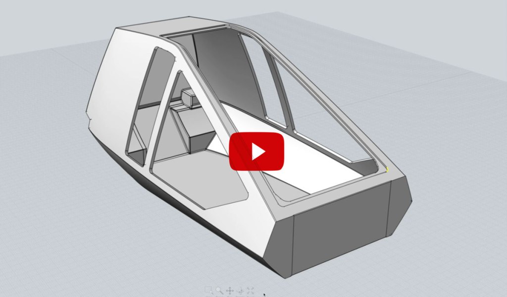
Here are a couple of videos showing the creation of the new chassis in the 3D application, Moment of Inspiration (MoI).
The first video shows creation of the outer shell or “skin” of the vehicles chassis. I have imagined that the workbee’s body is a type of composite frame or shell, with the various window, door and panel openings integrated into the shells fabrication. In 3D modeling terms, this outer skin will have the inner shape “subtracted” from it, making it a hollow shape with walls of a specific thickness. Then the panels, windows and doors are “cut” into the shape.
The second video shows the creation of this “inner” shape, subtracting it from the “outer” shape. I then use various “cut” shapes that I had previous created for the previous partially completed version of the workbee 3D model. I use those components to knock-through or “cut” into the chassis shape to create those openings.
At various stages throughout the process I fillet the edges so as to make them rounded as most real-world objects are. This is important for objects that people handle or come into contact with. Sharp corners and edges can cause injuries if the edges are not rounded.
In the context of a vehicle or object in space, having all exposed edges and corners rounded is be critical. A Starfleet workers life would be on the line during an EVA when it comes to rounded surfaces. Accidentally snagging your space suit on a sharp corner, or slicing open a glove when grabbing a hold of some exposed component would make for a seriously bad day at work.

This is one of the reasons I have always tried to work from the mind-set of an “in-universe” perspective and pay attention to “real-world” details that are implied from the various filming miniatures, sets and props developed for Star Trek: The Motion Picture.
This includes working out elements that are not actually visible in the film or in its props and miniatures. Things such as how seals and gaskets, structural framing, electrical wiring, fasteners and such are designed. Working out the ergonomics and functionality for construction, maintenance, etc. is something I try to consider and makes for a more convincing design rationale.
This all harkens back to the core design ethos that form follows function.
Now that I have the basic chassis corrected, I hope to move on to modeling the actual underside components and detailing in the coming weeks.

Long-term I have always intended to create hyper-accurate “blueprints” for the workbee. With the discovery that the original Kimble blueprints, upon which almost all the fan-crated artwork and 3D models of the workbee have used as their basis is inaccurate, a new set of blueprints which show the correct details and proportions will hopefully be of interest and benefit to other Trek geeks and “rivet counters” out there.

Fantastic work
LikeLiked by 1 person
Thanks Gerard. I appreciate that others actually have an interest in seeing my Trek-geekdom work.
LikeLike
Nice to see you back at it! Loving the detail and narration. Glad to see you finally found a under-side ref photo of the work-bee.
LikeLike
Hey Man great work on this. Would love to see those reference pics of the underside of the workbee. The only reference I can find of the bottom is other people’s 3d models, which aren’t accurate. Yours is the best yet. I have to redo mine now. So thanks for that ; ) Definitely will get a set of your prints when done, as I have noticed the problem at the back corners on Dave’s blueprints. It drove me crazy trying to figure that out. Can’t remember what I did on my Lightwave model. Have to dig it out. Did you ever figure the overall size of the studio model. Christie’s auction lists it at 18 x 8.5 x 8 inches. Building a studio scale model, that’s why I’m asking. Again great work. Love that someone appreciates the little gal like I do, Cheers,
Joe
LikeLiked by 1 person
Thanks Joe. I truly appreciate your comment. Unfortunately I’m not at liberty to share the actual reference images of the underside of the filming miniature, as the person who gave them to me did so under the agreement I would not post them. Hopefully he will ease up on that stricture so I can share them.
I know that Eaglemoss’s Ben Robinson has a massive trove of super high resolution reference images of the filming mixture, but he isn’t sharing them with me despite his saying at the STLV convention back in 2018 that he would (which is a real pisser). Which is ironic in a way given how inaccurate the Eaglemoss Workbee ended up being when they produced it.
Anyway, as to the overall size of the filming miniature, as you no doubt know, it was built at 1:6 scale and the chassis measures 18.125″ from front tip to back, 8″ in width at its widest point, and 8″ in height for the main body itself.
However, the aft/top “spine” which houses a bunch of greebles in the back and the top-side running light on the top, extends beyond the above chassis dimensions by approx. 29/64 of an inch on the top (0.459415 to be precise) on the top, and by 1/2 inch at the rear.
Hope that helps.
LikeLike
Thanks for the quick reply. Yea, I know all about the secret share ; ) I’m on a lot of studio scale modeling forums and there are the sharers and the hoarders. I don’t get the secrecy thing cause I’m a sharer myself. But I understand when you have to agree to it. I had to actually sign an NDA to buy a set of blueprints years ago. So no harm there. I appreciate the confirmation on the dimensions. I have a side view of the blueprints from Dave blown up to that size. I even bought a GI Joe to sit in it. LOL. He’s a beardless one to better match Star Fleet regs. And he was cheaper, ; ) Anyhoo, I’ll try to find the pics of my mock up so you can see what I’ve got so far. Haven’t done any video for the tube yet. Again thanks and keep the videos coming, it’s better than most stuff on tv, cheers,
Joe
LikeLiked by 1 person