
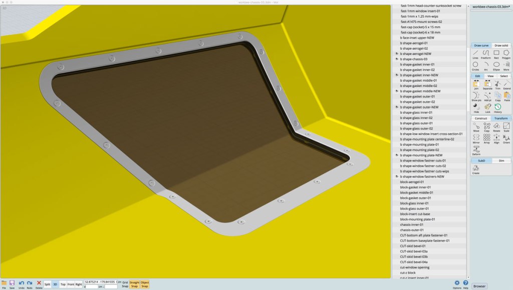
I finally completed modeling the mounting hardware for the underside windows on the workbee. It actually entailed rebuilding the inside “window” edge of the components. This was due to not leaving the inside face of the window opening vertical. Instead I had it at the 41.5º angle which is the average outside slope of the underside angled hull in the area of the window location.
This error would require the mounting screws on the inside of the assembly to have to be tapped into the comments and into the chairs frame at the aforementioned angle. Needless to say that was not what was intended and would not be at all workable.
The solution was fairly simple and straight forward. have the outer face on the inside edge of the components cut into the chassis at the 41.5º angle as before, but have the inside face go up vertically at a 90º angle. This makes each component in the window assembly progressively wider on the inside section.

This was not at all a problem for the final. It was a quick fix, and makes the mounting plate have more surface area. But more crucially, it allows the mounting screws along the inside section go down vertically into the chassis frame.
Here is a quick video which shows the mounting plate with the countersunk holes for the screws, the fasteners themselves, them building out the gaskets and aerogel layer:
I omitted showing the transparent aluminum windows panes, because Moment of Inspiration doesn’t actually render transparent materials. It is after all a NURBS modeling application, and not an animation/rendering one.
I did start playing around with different object styles. Setting up different colors and also disabling having the edge line segments display. The edge lines are critical to have display when actually building and editing objects in the application, but tend to make visual display more cluttered.
I’m also slowly refining the video editing as well. This is helping me improve my FinalCut Pro skills. I still haven’t invested a huge amount of sweat equity to really have the most efficient workflow within the application. I’m probably doing things that hard way in this self-teaching method of just jumping in and doing it. But I do feel I am getting to understand the program more each time. This is one reason I have been posting more video content instead of still image/illustration stuff.
Anyway, I am pleased to finally have this mounting hardware modeling completed, and will start in on the “package monitor/control contact point” panels I discussed in the previous post.
