
This past week I spent working out the precise design and shape of the underside windows of the workbee. While at first blush, this would seem to be a fairly straight-forward task, working it out as if it were a “real” vehicle that would need to operate in the vacuum of space made it pretty challenging.

In fact it took multiple different attempts (and approaches) to get the size and shape of the multiple components that would make up an airtight portal. If the window was imagined simply a single sheet of transparent aluminum welded to the outer chassis, it would have been fairly straight forward.
In the 23rd century (the setting for Star Trek: The Motion Picture) transparent aluminum is a material that has been invented and is used a construction material that is far stronger and more durable than its polymer-based predecessor, plexiglass.
As shown in Star Trek IV: The Voyage Home, a one-inch (2.54 cm) thick sheet of transparent aluminum, measuring sixty feet (18.288 m) by ten feet (3.048 m), was capable of withstanding the pressure of 18,000 cubic feet of water, which could be used in place of a six-inch thick sheet of plexiglass.
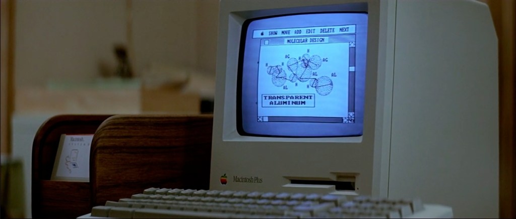
Macintosh Plus displaying the molecular formula for transparent aluminum in 1986. From
Star Trek IV: The Voyage Home.
Plexicorp logo. (Image: Courtesy The Star Trek Design Project)
In the film Dr. Nichols of the fictional San Francisco-based Plexicorp, acquired the formula for transparent aluminum in 1986 from a mysterious engineer from Edinburgh, known as “Professor Scott.” In exchange for the formula, Dr. Nichols provided enough Plexiglas to “Professor Scott” to construct a giant whale-tank in the cargo hold of the stolen Klingon Bird-of-Prey.
Interestingly, a few years back researchers at the Surmet Corporation developed an optically clear aluminum oxynitride ceramic armor material called ALON® which has been dubbed “transparent aluminum”. So once again life imitates art when it comes to Star Trek inspiring scientists and technology.

All that aside, as mentioned previously if it was simply a sheet of transparent aluminum welded to the outer chassis, it would have been fairly simple to work out the geometry for the window shapes and create said piece for the underside windows. However this would not facilitate an imagined “in-universe” replacement of a window if needed by Starfleet personnel.
If the outline of the window was simply projected onto the outer surface of the chassis, and “cut” into it, it would produce a piece which would have a wedge-shaped cross-section. You can see this in the diagram below:

This would not be an issue if the window was surface mounted on the exterior with an inset sill to attach the piece onto. But this would not allow for removal or replacement of the window if damaged or needed repair without cutting the welded transparent aluminum window out of the chassis. In addition this would not be the ideal way to attach a pressure bearing window face which would have an atmospheric pressure (also known as barometric pressure) in the inside of the cabin with an average of 1013.25 mbars (millibars) or 14.696 psi (pounds per square inch).
So ideally Starfleet would want a design that is mounted from the inside so the internal cabin pressure pushed the window faces outward against the chassis frame. The would lead to a more robust fitting that would not be as susceptible to joint failure and would actually increase the effectiveness of any seal along the joined seams. But in order to have removable set of window panes/surface they would need to either have parallel edges in cross-section, or preferably a slightly inverted wedge-shape cross-section as shown in the diagram below:
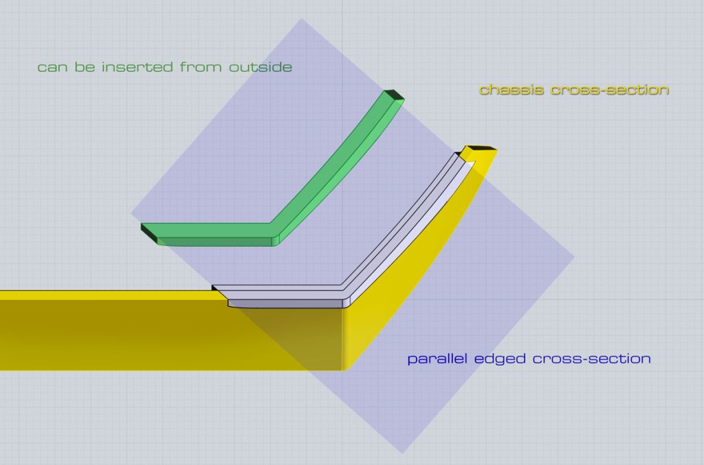
This would allow the window components to be pushed into place from inside the cabin, and secured into place against the inside of chassis frame. But as mentioned at the outset, this made me do quite a bit of experimentation within Moment of Inspiration to correctly model the shapes in order to produce this inverted wedge cross-section. All while still intersecting with the outer face of the chassis in the precise shape of the visible outside window. This is because the outer surfaces of the chassis have very subtle compound curves (i.e. curvature in two directions simultaneously) to their surfaces.
In the image below you can see the “cutting” shapes I finally created, which allows the proper intersection through the outer chassis shape:


These shapes were then used to “cut out” the various layers which were offset from the inside surface of the chassis. The layers were worked out to precise thicknesses in an imagined cross-section of components such as a double pane of transparent aluminum (i.e. “glass”) with a triple layer of gaskets to seal any pressure leaks and with a layer of aerogel to insulate the inner window from the extreme temperatures that the outer window and chassis surfaces would be exposed to in space.
I previously discussed what aerogels are in a post awhile ago. While the name implies that it is a soft or rubbery material, in actuality it is a fairly rigid material. Which, while somewhat brittle, can hold up under an even moderate compaction, well within the range of what would be expected in order to retain a variable interior cabin pressure and the occasional foot pressing, etc.
In the video below, I show a cross-section for the final window components I worked out. It also does a quick “fly-around” showing the window inserts in position within the chassis.

I still need to work out the precise positions and angles to model and “cut” in the countersunk mounting screws which hold the entire assembly in place against the inside of the chassis’ frame.
Next up, I need to model the side “package monitor/control contact point” panels, highlighted on the original David Kimble blueprint drawings from 1979:

The lessons learned from working out the underside windows will help out in making those go a lot easier. That and the fact they only intersect with one exterior face on the underside will make it much, much simpler in design.
That said, it is not entirely clear exactly how these “contact points” were designed to function “in-universe”. From the images of the filming miniature, these are simply scribed panels in the exterior surface of the chassis, and are painted orange (the front two) and orange/yellow (aft panel).
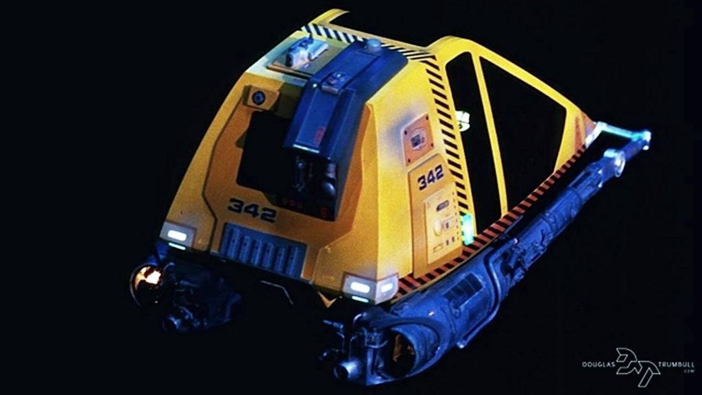
In an image from Douglas Trumbull (who was the director of special effects for Star Trek: The Motion Picture) it shows that these panels did not open up when the manipulator arm package was attached when viewed from above:
Likewise, from the screen grab from the film itself, it doesn’t show the panels open from below either:

This leads me to imagine these might be similar to grappler pads that were part of the anti-grav handlers shown in the original series, but with some sort of integrated 23rd century type of Wi-Fi near field control transmitter/receiver capabilities. Below is some images of the anti-grav devices from the TOS episodes “The Changeling” and “Obsession“, and a diagram of it from Star Trek Fact Files – File 59 – Card 18.

Diagram of the anti-grav devices from Star Trek Fact Files – File 59 – Card 18. 
Spock and Scotty arrive in engineering with anti-grav devices, from the Star Trek: The Original Series season 2, episode 8 “The Changeling”. 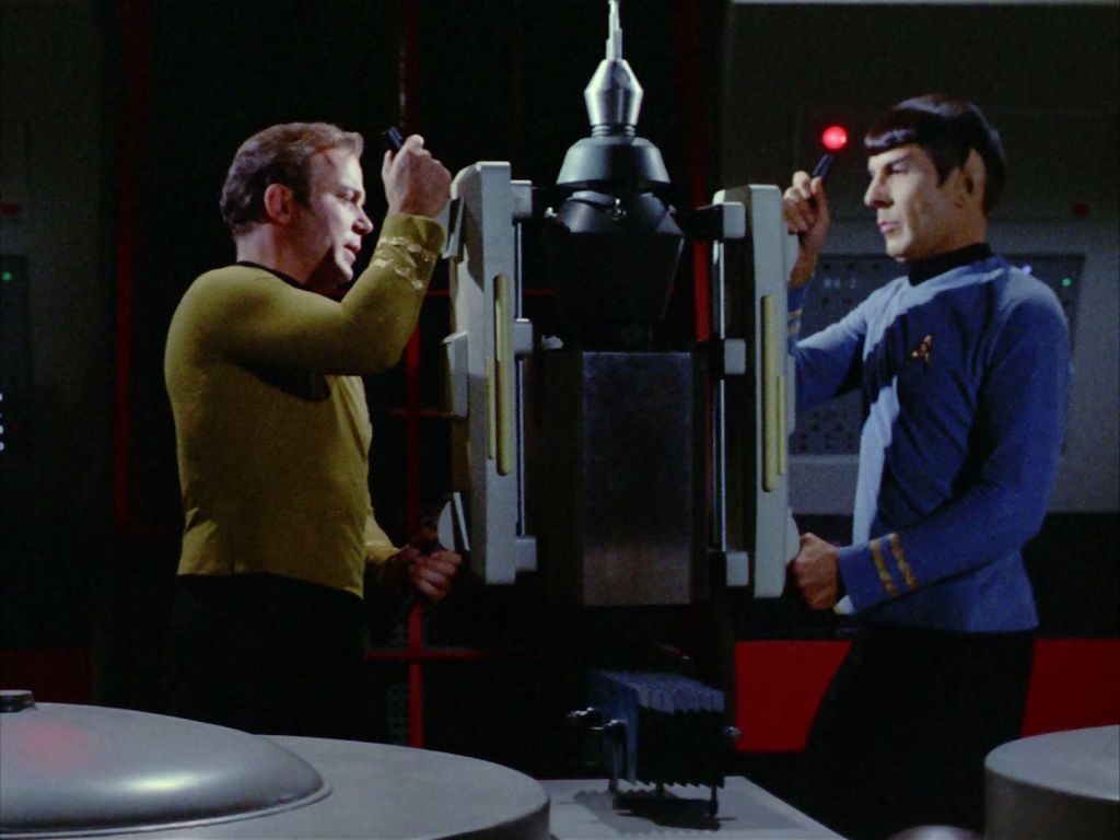
Kirk and Spock place anti-grav devices on Nomad in engineering, from the Star Trek: The Original Series season 2, episode 8 “The Changeling”. 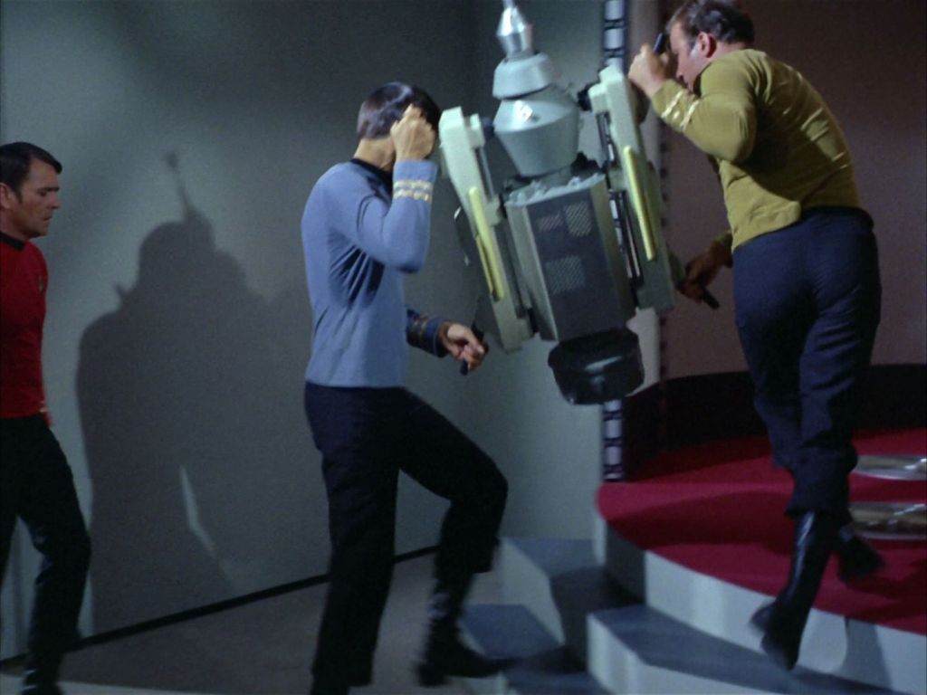
Kirk and Spock carrying Nomad with anti-grav devices to the transporter pad, from the Star Trek: The Original Series season 2, episode 8 “The Changeling”. 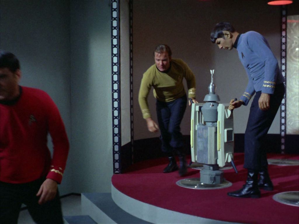
Kirk and Spock place Nomad which is being held with anti-grav devices on the transporter pad, from the Star Trek: The Original Series season 2, episode 8 “The Changeling”. 
Close-up of Nomad held with anti-grav devices on the transporter pad, from the Star Trek: The Original Series season 2, episode 8 “The Changeling”. 
Nomad held with anti-grav devices on the transporter pad, from the Star Trek: The Original Series season 2, episode 8 “The Changeling”. 
Captain Kirk and Ensign Garrovick with the anti-grav device carrying an ounce of antimatter, from the Star Trek: The Original Series season 2, episode 18 “Obsession”. 
Captain Kirk and Ensign Garrovick with the anti-grav device carrying an ounce of antimatter, from the Star Trek: The Original Series season 2, episode 18 “Obsession”. 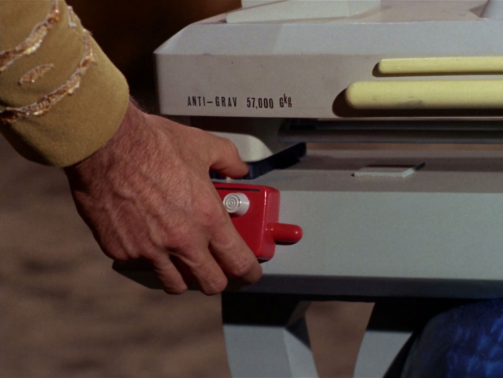
Detail of the anti-grav device from the TOS episode “Obsession”. 
Presumably the gripping technology in the anti-gravs are similar to what Franz Joseph described in the original Star Fleet Technical Manual page on the Type II hand phaser as “magnatomic adhesion areas”, though in reality the phaser props simply used velcro-strips which had been invented just several years earlier, to get them to stick to their hips when wearing their uniform costumes.
That said, the contextual clues that these need to be some form of gripping mechanism are that they are the main contact points on the side of the workbee for the cargo-train package.

Star Fleet Technical Manual diagram by Franz Joseph highlighting the “magnatomic adhesion strips” on the
Type II hand phaser.
Photo of the original workbee and attached cargo train filming miniature built for Star Trek: The Motion Picture, from Douglas Trumbull‘s defunct website.
Yet they are clearly listed as a “package monitor/control contact point” in the Kimble drawings. So this is why I am leaning towards a combination gripping communication contact panel. At any rate, that’s the direction I am probably going to take when working out these mystery panels.
Interesting aside, there is a similar panel aft of the larger rectangular which is not shown in the Kimble drawing. It is immediately behind the larger rectangular one but not as tall, and the top edge angles down with the back edge roughly the same height as the secondary thruster alcove face where the thruster port(s) are located and it appears on both the port and starboard outward faces. They are the same color (yellow orange) but for some reason, they are simply excluded from the Kimble blueprints.
After I work out those contact panels, the last exterior details I need to model are the “hard-docking attachment-point doors” near the front nose and the actual secondary thruster ports at the back (along with a generic dark gray rectangular panel attached the lower aft center boss/pylon extrusion. Then on to the interior modeling.

Pingback: Screw the Window Frames | Third Wave Design