
I have spent the past few evenings, when not battling driving during a snow-storm that shut down the Portland metro area, working on 3D modeling some of the parts of the workbee spine.
I finally gave in to my mania. Instead of simply modeling for the purposes of the micro-scale 3D printing of the workbee pieces, I have gone into full engineering/industrial design mode for the various components that detail the spine of the workbee.
The first step was to try and make out as best I could, what shapes could be gleaned from the scant few photos of the aft and top-side view of the original filming model. This is not as easy as it sounds given the dearth of images, and the lack of detail that can be reliably worked out from the few that do exist.
So working and re-working shapes that would roughly match my best guess as those original model parts and shapes were, and then coming up with what the piece might be on a “real” workbee, ended up being multiple evenings worth of work.
As before, trying to arrive at a plausible function for what components are shown, which in turn inform its design, all while maintaining a decent match to the guessed shapes, was no small challenge. Likewise, I went ahead and converted everything to metric, which is what is used in the Star Trek universe, and idealized all dimensions to the nearest ones that would make sense at full size.
So just as with the cargo pod labels I worked on previously, I have been pondering a lot about how the various components for the workbee would be engineered. I have tired to pay close attention to the functional needs of the theorized craft, and the environment it would need to operate in.
This lead me to looking at current materials for industrial design, as well as emerging ones, that would handle the incredible temperature ranges of deep space that a workbee would need to function in. This would mean temperatures approaching the background cosmic radiation temperature which is only a few degrees celsius above absolute zero. A temperature astrophysicists have worked out to be roughly -270.6º celsius (or a mind-numbing -455 degrees Fahrenheit). That’s down past the temperature of liquid hydrogen and other cryogenic liquified gases.
So what materials would be usable in such an insanely cold environment? And more to the point, how would you protect the occupant inside the workbee from such temperatures, to say nothing of radiation, etc.?

Flower sitting on, and protected by
a piece of aerogel, over a open flame.
The answer is in materials such as aerogels.
Aerogels are actually more a process of making composites and alloys, rather than specific chemicals or elements. Though certain elements and compounds are better suited for the type of applications aerogel alloys would need to be made up from.
Aerogels are basically materials which are “dried” in a certain way when they are formed which create nano-scale pours within the material. It leaves a material with a massive amount of molecular-sized pockets of “air” or gas trapped within and making up a super-fibrous structure.
All these molecular-scale pockets of trapped gas act as a super efficient form of insulation. This is similar to how energy-efficient windows work by having the space between air-tight panes of glass filled with gases that are poor-conductors of heat (or cold).
Aerogels are the most efficient form of insulation humans have managed to come up with to date. It is some really crazy material and really fascinating stuff. A huge amount of the material is actually composed of nothing which makes it super lightweight. Most aerogels are made out of silicates which, because it is mostly air, give it a ghostly translucent color. Scientists and engineers have often called the stuff “frozen smoke” for this reason.
It is a very, very strong material with some of the highest strength to weight ratios around. It can handle compaction very well, though it is often fairly brittle. I envision it beings the main carrier in paint polymers used for coating the interiors and exterior of the workbee.
Old-school G.I. Joe visible in the original filming model.
That said, most compounds used in making aerogels actually leave it translucent. As such it is currently being developed under various brand names (such as Lumira) as a component in architectural glass. This gives windows made of aerogel material some of the best insulation ratings around. Better than traditional fiberglass insulation if you can believe it.
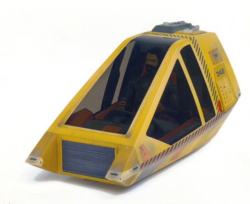
So that actually lead me to come up with a justification as to why the workbee has tinted windows. I mean at first blush, having tinted windows in a vehicle designed to operate the dark night of space, where you have to light everything up with floodlights, etc. seems silly.
Of course the reason the original filming model of the workbee had tinted windows was to help obscure the fact the the 18″ model had an old-school 12″ G.I. Joe (with life-like hair and the kung-fu grip) as the pilot. So having the windows very dark allows you to sort of tell their is a person in there, but you can’t really make out that it is a doll.

Gold and indium vapor-coated canopy of the
F-22 Raptor fighter-jets.
But the need for thermal protection for the pilot/worker within the vehicle, as well as radiation protection, is the justification for an aerogel window polymer which “tint” the windows.
Aerogel made of silicon and indium and gold coating would give it the dark amber tint.
Here in the 21st century Indium, a chemical element, is used in vapor deposited coatings of fighter-aircraft canopies. This is done in order to reduce radar signatures and block electromagnetic energy from penetrating the cockpit. It is what gives that gold reflective color to modern fighter-jet canopies when viewed from an acute angle.
The aerogel component of it would make it so you would not get instant frostbite and tissue damage from touching the inside of the workbee window while out in deep-space. And the coating would shield the pilot from any solar radiation from nearby stars as well as background cosmic radiation.

Space Shuttle Endeavour showing the silver radiators
which line the inside of the cargo bay doors.
This would be why most surfaces of the workbee would be painted or have some sort of aerogel baked-on powder coating. To insulate and shield the equipment inside as well as the pilot.
The flip-side of the extreme cold of deep space is that most space vehicles need to be able to bleed off heat from on-board equipment. In fact that was one of the first things the Space Shuttle used to have to do once it got into orbit. Open its cargo bay doors to allow the thermal radiators which lined them to begin to dispute heat.
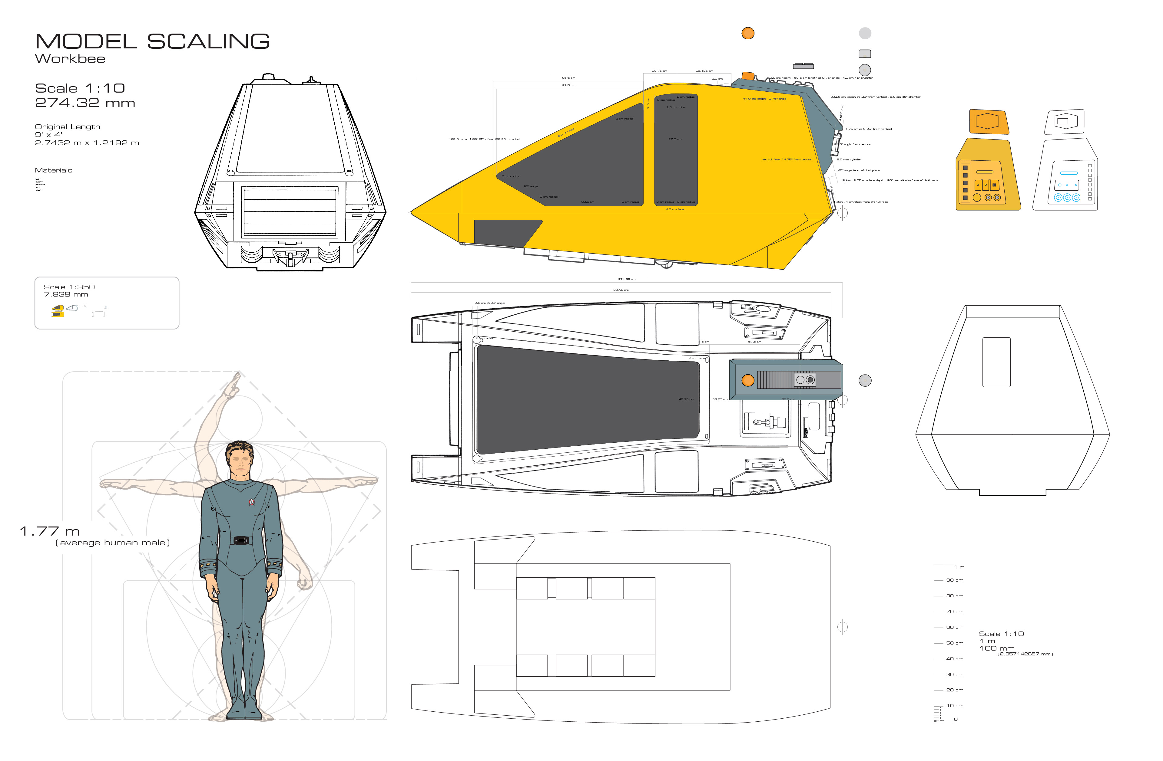
This would explain the exhaust vent slats clearly visible on the center-top of the workbee spine (and specifically labeled in the Kimble blueprints). I also envision that the numerous “black rectangles” which are in clusters on various equipment panels on the aft portions of the workbee are vent perforations. I will design them to be openings in the hull behind which would be heat-sinks would sit for various piece of electronics and equipment within the space frame.

Top view showing the workbee’s exhaust vents on the spine. Photo courtesy of Doug Drexler’s website.
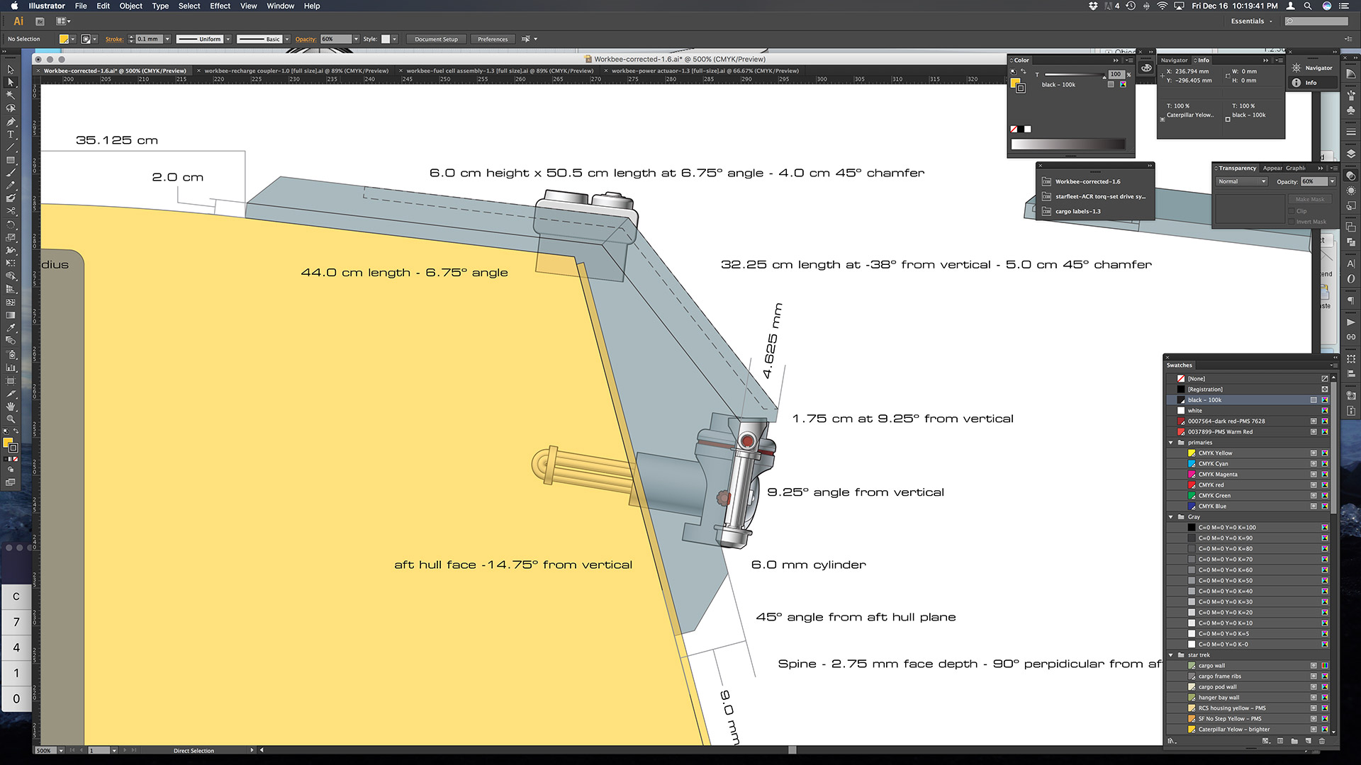
The first main piece of exterior equipment on the aft spine I worked up was what I dubbed the “auxiliary power actuator arm”.
Basically the spine, as near as can be deduced from both the original David Kimble blueprints from the original release of Star Trek: The Motion Picture, as well as what makes sense from the production illustrations that Andrew Probert came up with when designing the original models, is basically a housing for the power plant of the workbee.
As is shown in the original blueprints as well as the matte painting sketch Mr. Probert did, there is a recharging connection port as well a fuel port on the top of the spine.
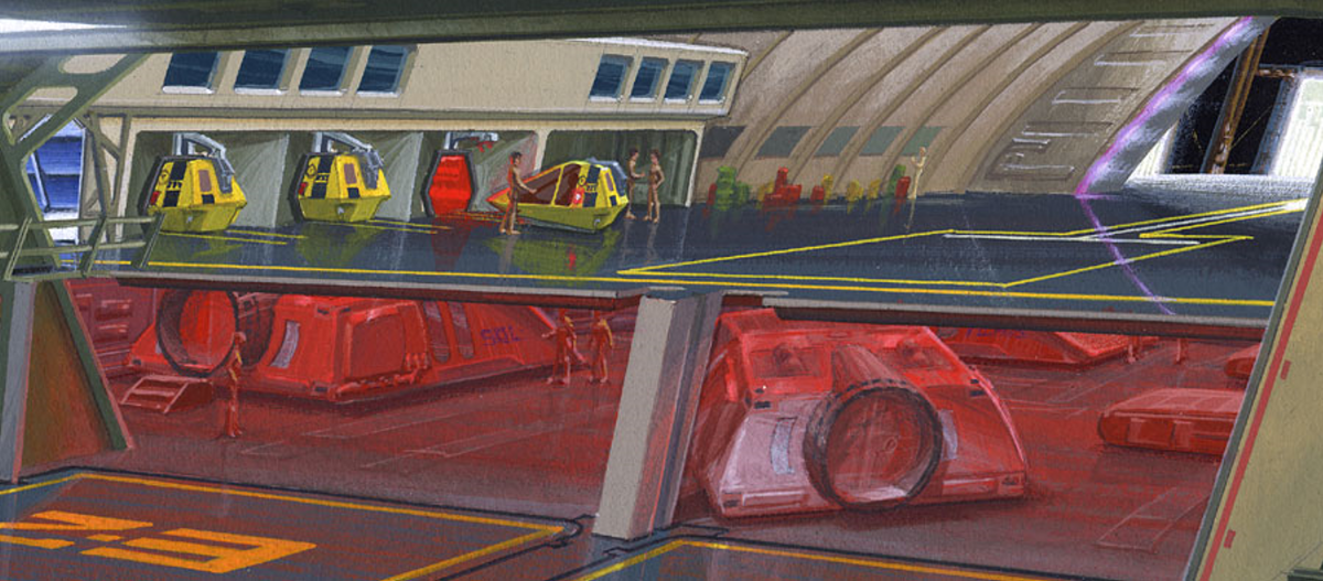
Detail of Andrew Probert’s matte painting sketch,
showing the workbee recharge stations.
That said the workbee was intended to be a modular system. Mr. Probert has mentioned, and the Kimble blueprints explicitly state that the workbee acting as a “cab” that can plug into, various equipment attachments, or have said attachments coupled to the workbee. Some of the attachments are sets of manipulator arms or “sled” attachments. Others are the cargo train attachments, which can be loaded up with the cargo pods discussed last week.
The upshot is that these various attachment packages would often need to be powered from the workbee’s power plant. So the lower back portion of the spine has various electrical power plug-in points. Presumably some attachment packages have the power connector integrated in them and would “plug-in” to the workbees power system. However some would no doubt have a female power port and therefore need the workbee to “plug-in” to it.

Work-in-progress 3D design for the workbee’s Aux. Power Connection Actuator Arm.
One of the pieces you can see in the original model has what looks like a telescoping or piston-rod type piece of gear. I took that shape and made it the logical choice for modeling it to be a articulated motorized arm which houses a power connector. This arm could extend and rotate and tilt in order marry with the power-port sockets. The assumption being that those ports would would be in various locations depending on the various design configurations of the auxiliary equipment packages.
So I worked out a design which roughly matches what I could make out in the photos, and made it a fully articulating arm. It would also make sense that starfleet would have these types of power connections in a somewhat standardized form of plug.
I therefore made it so the plug-in connector portions of the arm matches the power-charging port shown on the top of the spine where the workbee is recharged when it is docked in its berth within the Enterprise (as shown in Mr. Probert’s sketches).
Standardization while having form follow function.
This actuator arm would also have to be fairly sturdy and be able to withstand being banged around by space construction pilots and such. I imagine it would also be able to be remotely controlled by the workbee pilot “on-the-fly”, with integrated smart-phone size video camera to allow “in-flight” changing of equipment in a EVA work environment. The arm would need to be designed in a way that the power cable and integrated fiber-optic data connection would be accommodated within the fully articulated joint, which allows the arm to move in all three axis.
All this still needed to stay within the size and shape roughly shown on the original model. So I also included mounted actuator motors on the arm, to match the hard-to-discern shapes around the main rod. These motors pivot the arm in the vertical axis, as well as extending the telescopic arm which has the power-plug receptacle on it. The housing itself would be motorized internally in the spine to rotate the arm left-right.
The next piece I worked on is what I dubbed the “fuel cell assembly”.

Detail of David Kimble’s workbee blueprints showing the
“main generator” as part of the spine.
As denoted on the original blueprints, one of the aft pieces in the lower spine is labeled “main generator.” So that lead to the larger question, what would the workbees power generation equipment be?
The vehicle is much too small to have the matter-antimatter power system the Enterprise and warp capable vessel would have. Even a fusion generator (which would be fairly common in the 23rd century) would be too bulky to say nothing of being a little dangerous to have in a work vehicle that bangs around in space construction sites and repair EVAs.
There’s a reason we don’t have nuclear powered cars.
It would also need to be one that matches the the blueprint labels which show both a power and fuel recharge port on the top of the spine.
So my solution was to assume, and make, this “main generator” a solid state oxide fuel cell system.
Solid oxide fuel cells (or SOFCs), as noted on Wikipedia, are electrochemical conversion devices that produces electricity directly from oxidizing a “fuel”. Fuel cells are characterized by their electrolyte material and a SOFC has, as its name suggest, a solid oxide or ceramic electrolyte.
Advantages of this class of fuel cells include high efficiency, long-term stability, fuel flexibility, low emissions, and relatively low cost. It simply requires a “fuel” such as hydrogen or carbon monoxide and oxygen which pass through the electrolyte material to create electricity.

Solid Oxide Fuel Cell assembly.
Note the ACR-Torq screw system I drew up.
A SOFC is made up of four layers, three of which are ceramics (hence the name). A single cell consisting of these four layers stacked together is typically only a few millimeters thick. Hundreds of these cells are then connected in series to form what most people refer to as an “SOFC stack”. These”stacks” can either be in a planar form, or in a tubular configuration.
I decided on using a tubular configuration with six long “rods” of conductors carrying the oxygen stream within them. Those in turn are contained within a larger fuel tube housing. This is set up as a double loop circulating configuration.
This configuration lent itself to matching the round “end of a tube” like structure seen in several of the photos of the original model.
Fuel cell assembly and the recharge housing shown
in their basic configuration.
In addition this fuel cell structure extends into the spine and lines up roughly with an alignment which would allow a vertical feed system with the refuel and tank storage sub-systems inside the aft compartment (which I have not yet drawn up).
I envision the end of the larger circulating tube housing to be something that you might need to have the ability to open up to swap out the electrolyte rods every now and then. So it would make sense to not have to disassemble the entire workbee to get at. So I designed the rounded “end-cap” to actually be a hinged plate that is securely fastened to seal it up before the fuel gases are pumped into the housing.
This also lead me even deeper into the crazy. To the point of researching and considering what type of screws, bolts and/or fasteners would be best for this type of craft?
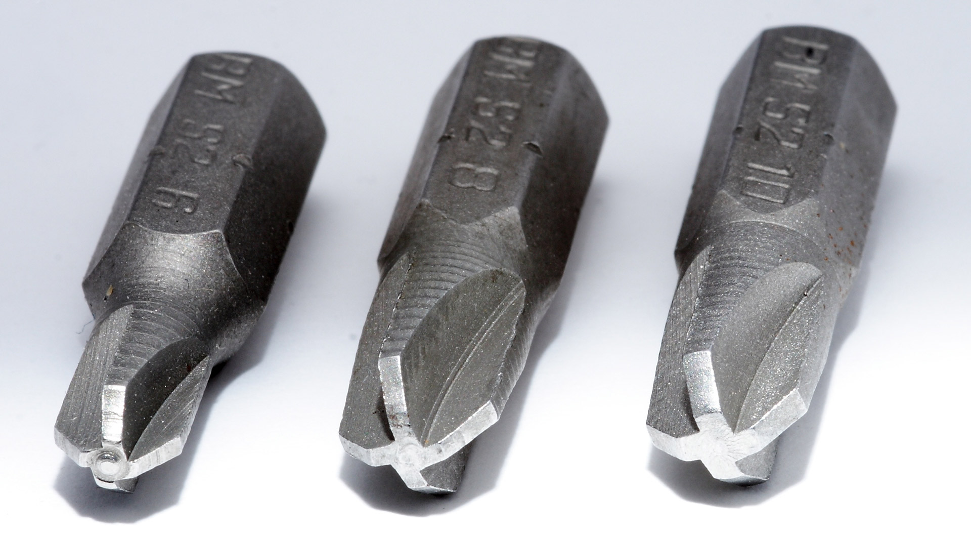
Real-world ACR-Torq Set driver bits,
which I based the starfleet version on.
Well that lead me to began reading up on the advantages and disadvantages of various types of screws. I now know more than I thought I could about screws. What screw designs work best, what their various pitfalls are, and which are used in what industries. I decided to pattern a standardized type of fastener for starlet on the ACR-Torq-set system which was developed by the Phillips Screw Company (which was started by a man from Portland) for the aerospace industry. It has the highest performance of screws and virtually eliminates the problem of “cam out” and striping the screw. And yes, there is a reason why this stuff matters for the aerospace industry.
Now at first that level of engineering seems crazy. But when you think about it, it actually makes sense. Do you really want to damage or make unusable a billion dollar satellite or stealth fighter because you stripped out a 45 cent screw?
The details matter.
Now since several bolt/fasteners are present on the exterior of the workbee (most notably on the aft upper side equipment panels) in the filming model, I went ahead and drew up the “starfleet” version of the Torq-set drive system, and modeled and incorporated them into the fuel-cell assembly as well.

Power and fuel recharge coupler on the top of the workbee spine. The power recharge port is the female mate
to the power actuator plug.
Lastly, that brings us to this evening when I drew up the coupler housing for the fuel and power recharging ports. It was actually fairly simple compared to the two previous pieces. Since I already worked out the “standardized” recharge plug design, I was able to make the female mate to the power actuator arm plug shape.
Hopefully tomorrow I will finally get to the point I can begin to work out and model the configuration of the louvered exhaust vents that are part of the top of the spine. Once I do that I can finally model the spine housing itself.
The other thing I have already begun to work out is that the spine housing is design in such a way that the outer housing hinges up. This is so you would be able to easily get at the guts of the equipment within the spine. It only makes sense from a usability perspective in the Trek universe.
That required me consider the thickness of the housing, the exact clearances and shapes of the housing so it can actually hinge up and “clear” all three pieces I worked up already since those are designed to be attached to the spaceframe inside the hull’s skin.
I realize I have gone way down the wormhole on this. But doing the hyper-detailed design work, down the the screws, and then working backwards from there to develop these “master” schematics, it is laying the foundation for “getting it right”. And it will be fairly easy at that point to then reduce down simplify the shapes in order to make the small-scale workbee printable for 3D printing. It will also leave me with fully detailed blueprints and the 3D models to make the larger scale workbee model down-the-road.
Plus its fun for me, in its own uber-geek way.

Pingback: Lounging On My Side | Third Wave Design
Pingback: Underside Windows | Third Wave Design